Blog — November , 2017
November 2017
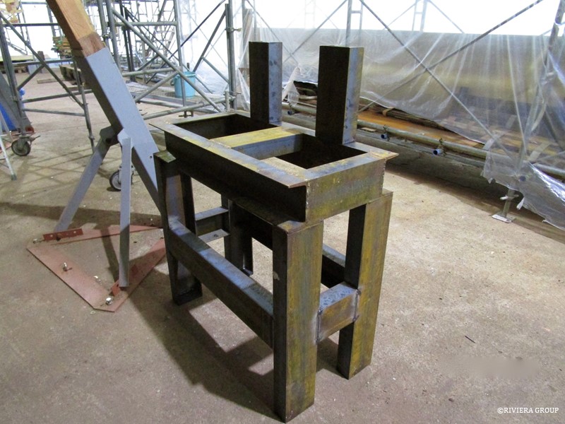
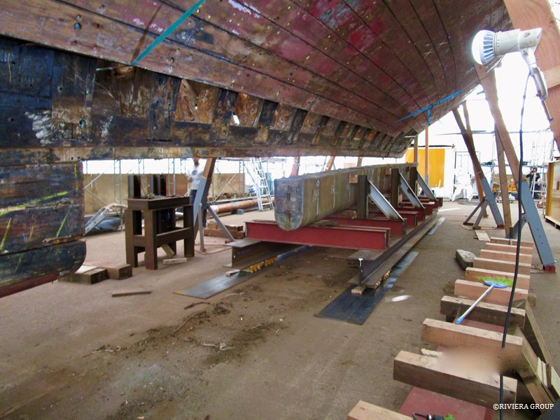
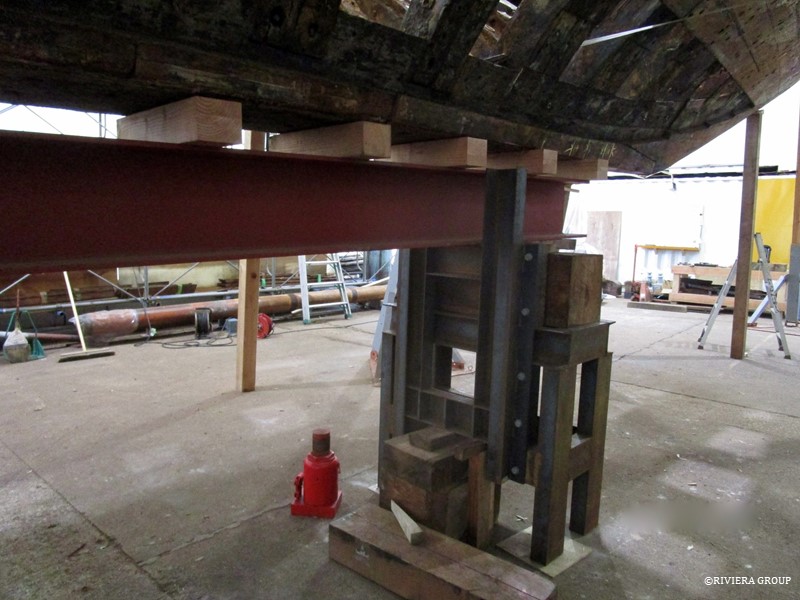
The plan to remove the ballast and straighten the boat moved ahead. It included the making of two heavy duty tables that would support the boat fore and aft. The tables (forward one above) were designed to support the strong back carrying the hull and allow height adjustments with the use of a 50-ton jack under each table. The ballast would then be lowered away from the hull.
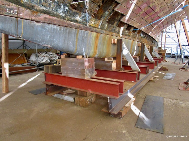
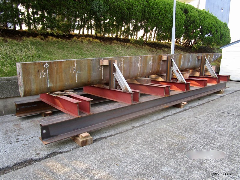
The ballast was supported on cross beams welded to two long I-beams (above).
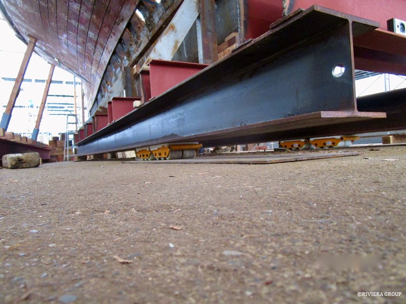
Skates were placed under the I-beams, so that the keel could be rolled out from under Cynara. The 8 skates, each with a 6-ton capacity, had to support the 25-ton weight of the ballast and the weight of the cradle.
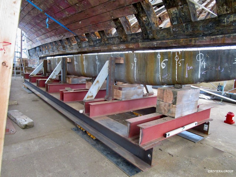
The boat was stabilized and the steel frame jacked up to meet the ballast. (The chalk lines mark the locations where the keel bolts ran through the ballast.) Blocks were used to account for the angle and the irregular shape of the lead. As the cradle holding the ballast was lowered, a gap appeared above the ballast (above).
When the gap was large enough to allow it, the 25-ton ballast began its journey to a new location. It was moved inch-by-inch with pulled by steel cables and turfers anchored at strategic points in the concrete floor. For turns, the corners were jacked clear of the skates, and the skates were set in the new direction before the cradle was lowered back down on them. Steel sheets were placed over the floor to reduce any strain from stones or cracks in the concrete.
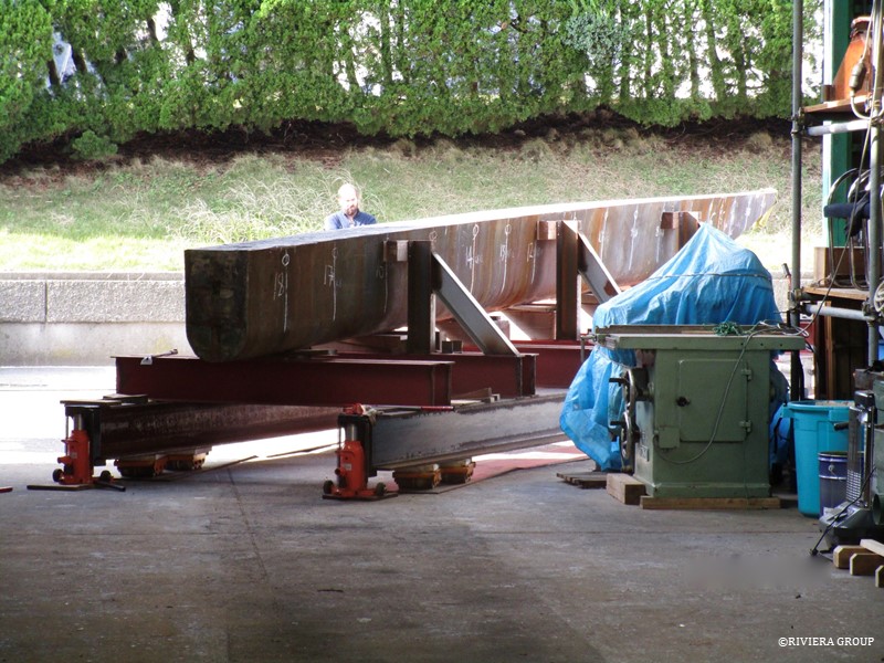
Lewis checking the angle of the skates as the ballast begins the final turn out of the machine shed. Though very slow, it was a remarkably smooth journey once everything was set. The hardest part was moving the awkward steel sheets.
The hog is clearly visible in this shot.
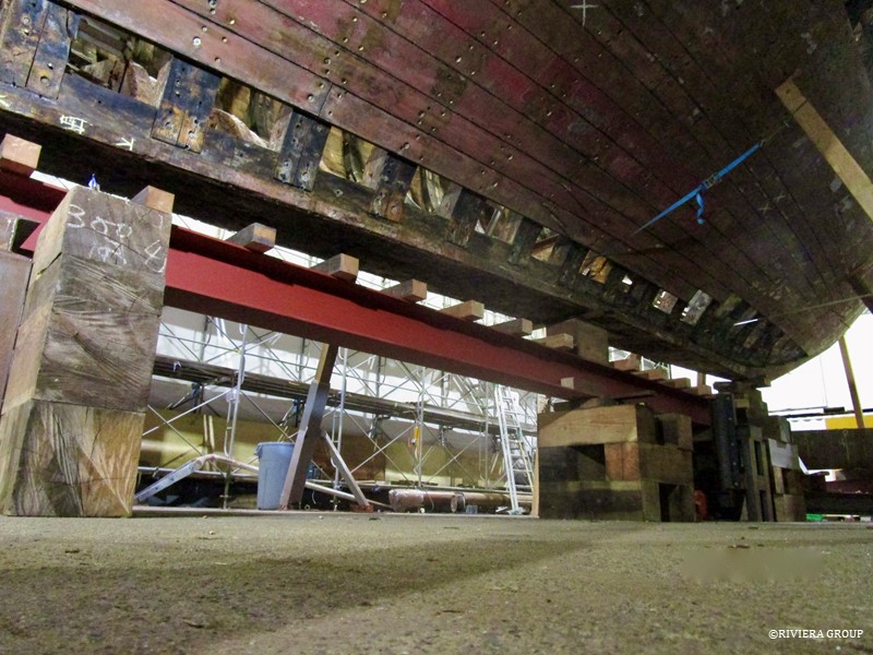
A strong back was created using four-inch blocks spaced evenly on an I-beam that ran between the two tables. This was then jacked up to the centerline to give the necessary support. The weight was taken by the beam and the tables, and the 4-inch blocks let us access any bolts in the underside of the keel. This was when she was at her most precarious, balanced on timber shores with nothing supporting the centerline. Now we could focus on straightening the distortion of many years in the keel timber, and jack it up to the correct angle.
Follow Us

Restoration by RIVIERA GROUP
Restoration photos by Yoichi Yabe & RIVIERA GROUP
Text and photographs copyright © 2019
RIVIERA CO., LTD. All rights reserved.
Email : pr@riviera.co.jp