Blog — August 13-19 , 2018
August 13-19 , 2018
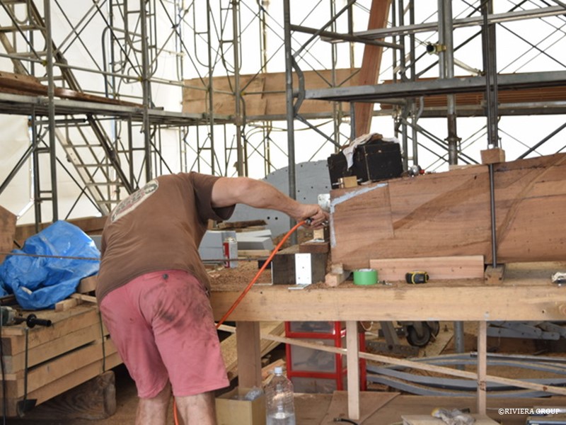
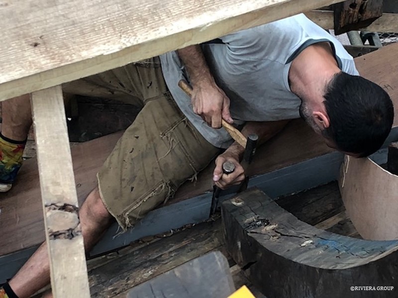
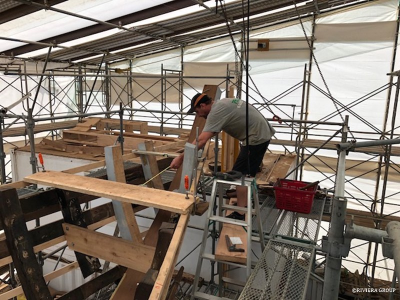
Richard makes minor adjustments to one of the housings or ‘boxes’ in the new stem section that will take the new frame foot.
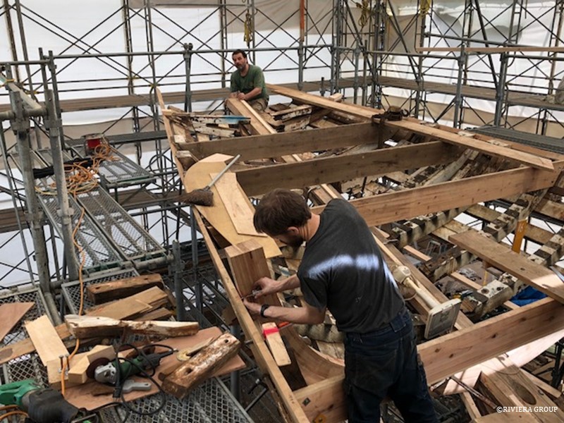
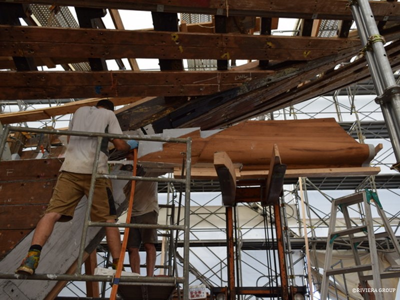
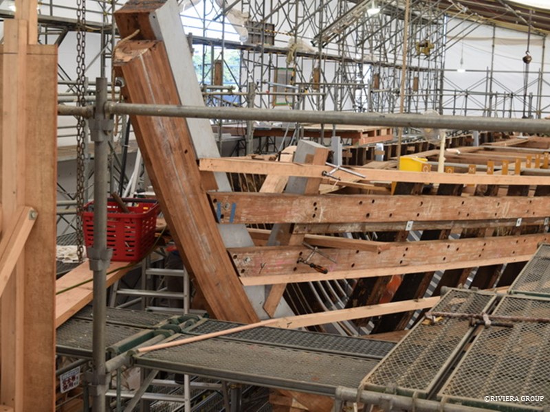
Mattis starts to fit single frames in the counter stern. It’s difficult to see here but the centerpiece of the hull in the stern (the horning timber) has been removed and will be replaced. The end of the timber was distorted and had defects that had not stood the test of time, so the aftermost half was removed and a new piece attached with a large scarph joint.
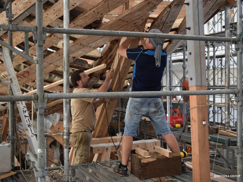
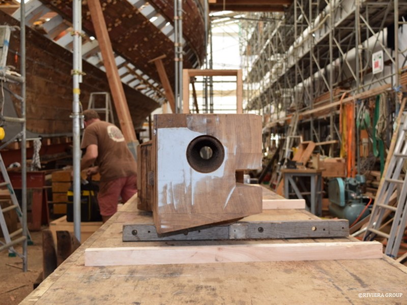
Paul and pascal feed the new horn timber section up between the planks through the open centerline in the counter stern for a test fit. If the horn timber is not centered correctly the entire stern and anything built here in the future will be off-center.
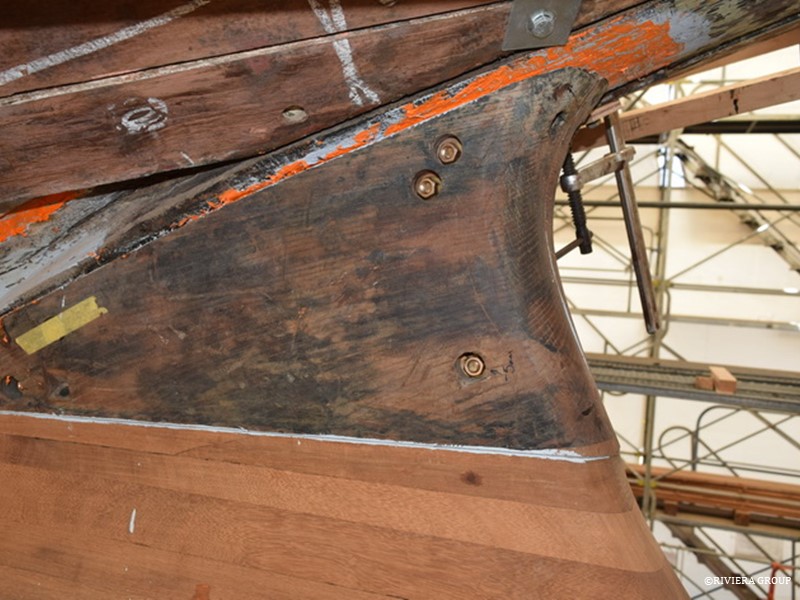
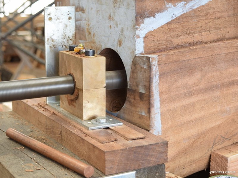
An infill piece above the shaft log fills the space above the shaft log and conceals the rudder tube that passes down through it. It completes the skeg section that is the top part of the rudder assembly. With Cynara’s unusual offset propeller shaft arrangement, the top third of the rudder is fixed and the rudder operates below the shaft exit.
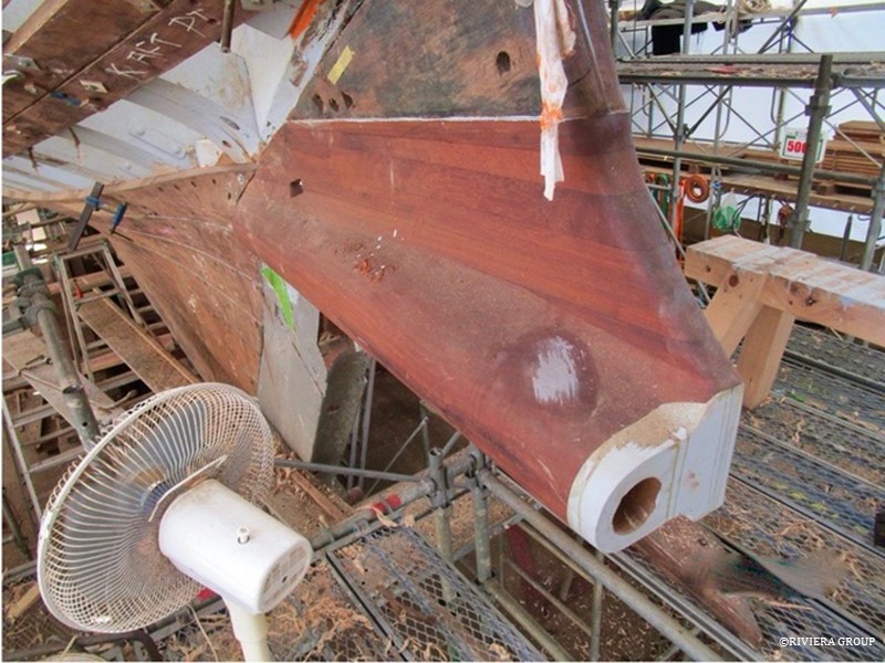
Cynara’s rudder swings below the shaft log (above), which places the propeller after the rudder.
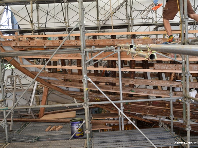
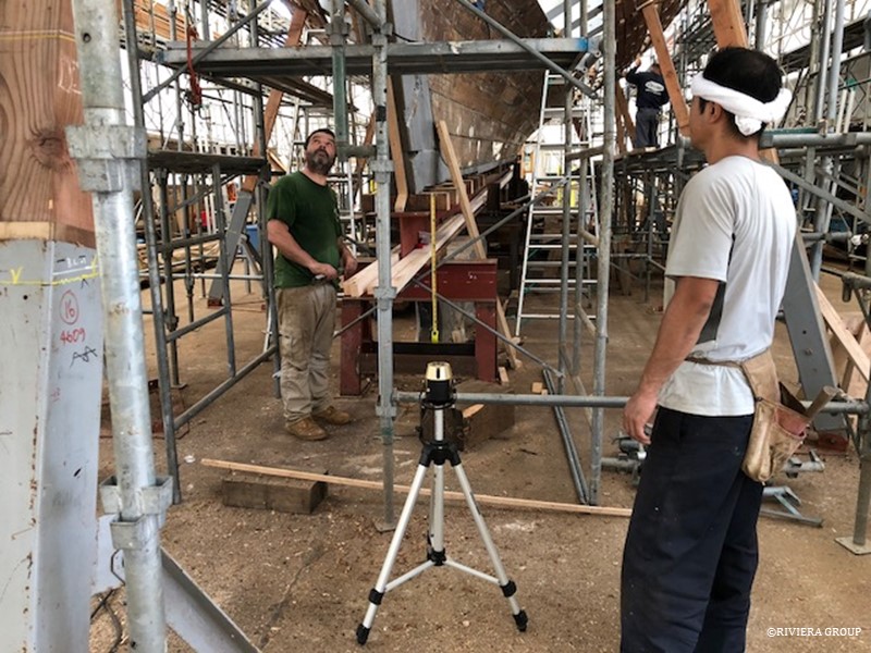
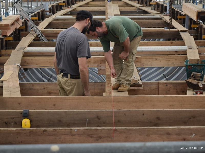
With the stem now in place, plank lines have to be set to ensure that the deck line remains true to the drawing, and the original planks can now be refitted in the same position they were in before removal.
Now that the lines have been checked and established in the bow section, Ben fits the four short single frames closes to the stem head. These are the smallest frames on the boat.
The stem head is waiting to accommodate the future bulwarks and bowsprit.
Follow Us

Restoration by RIVIERA GROUP
Restoration photos by Yoichi Yabe & RIVIERA GROUP
Text and photographs copyright © 2019
RIVIERA CO., LTD. All rights reserved.
Email : pr@riviera.co.jp