Blog —  October 2018

Blog — October 2018

October 1-15 , 2018

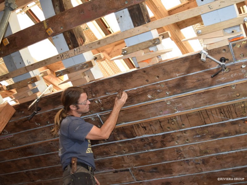
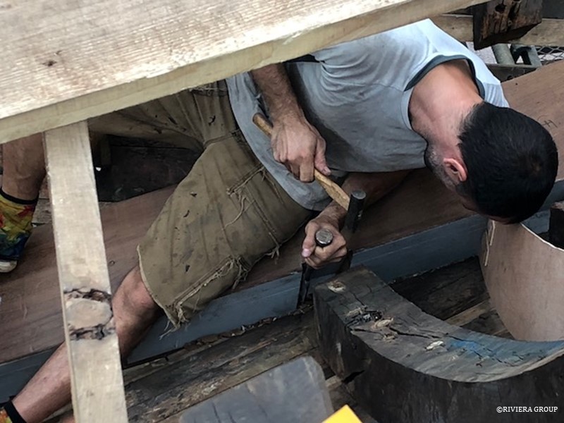
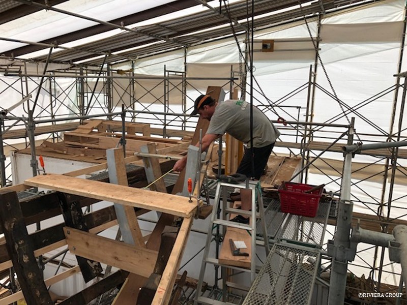
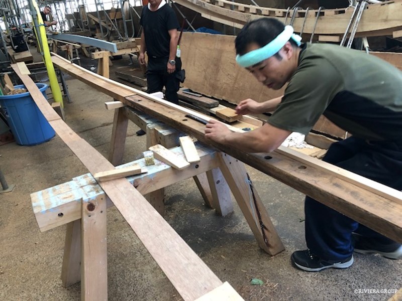
Kawashima is working on a plank that has had a new end scarphed and glued on. The scarphs are placed over a frame so that mechanical fasteners can be used through the joint into the frame. This ensures that should the glue ever fail, there would be a nail or a rivet to prevent the end of the plank from springing. We have confidence in the glue, but it’s always good to have mechanical fastenings to back it up. Kawashima uses a baton to check that the new plank section is fair with the old.
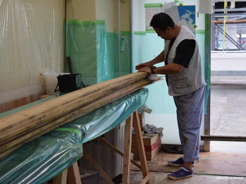
 

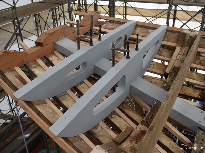
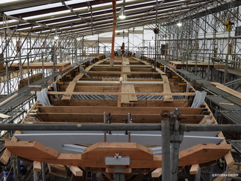
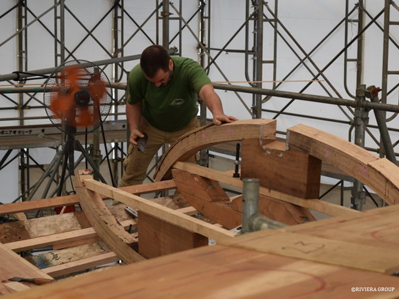
Deck beam laminations are now ready for the glue table. After carefully checking the moisture levels, the face of each laminate is scratched using a wooden plane with an old hack saw blade instead of a normal blade. The laminate face is scratched diagonally on both sides, creating a larger glue surface and allowing the glue to penetrate deeper into the wood fiber. Care is taken when setting the blade in the plane, because too deep of a scratch can break the fibers.
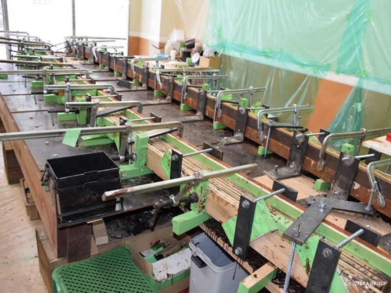
 

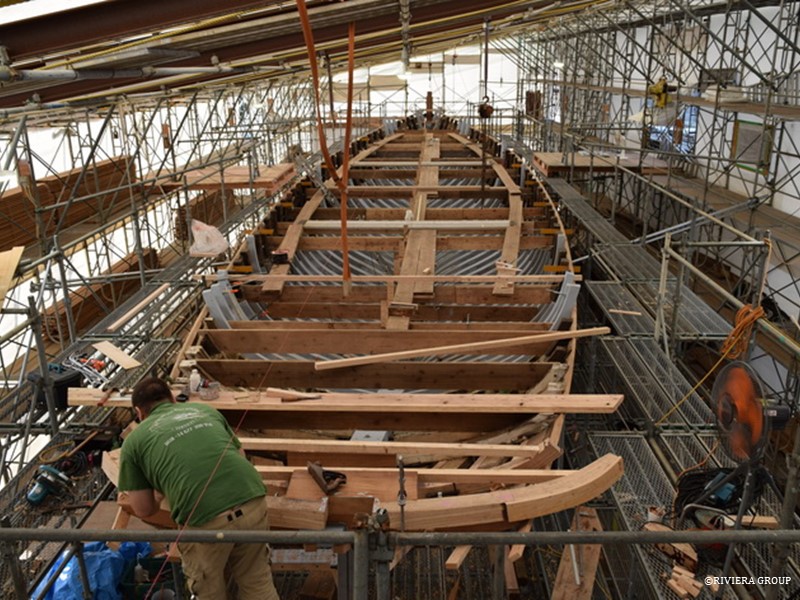
The first deck beams are in production
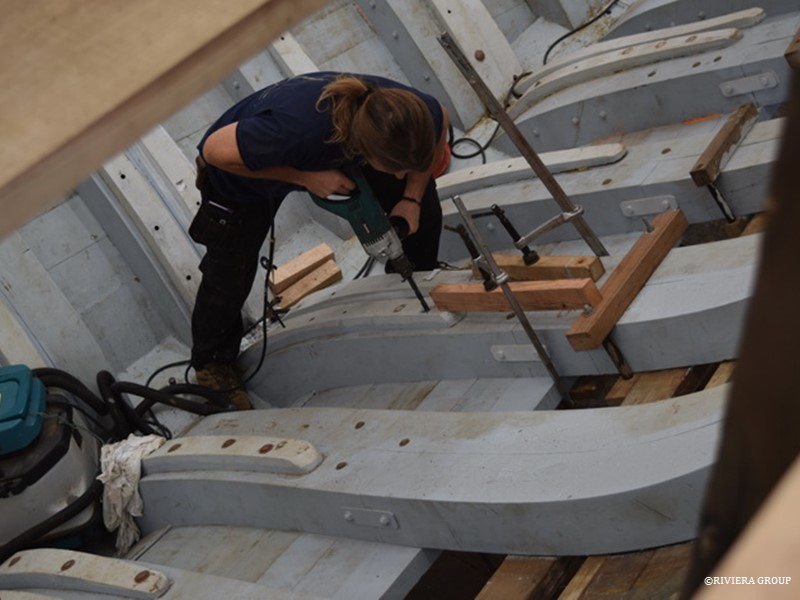
 

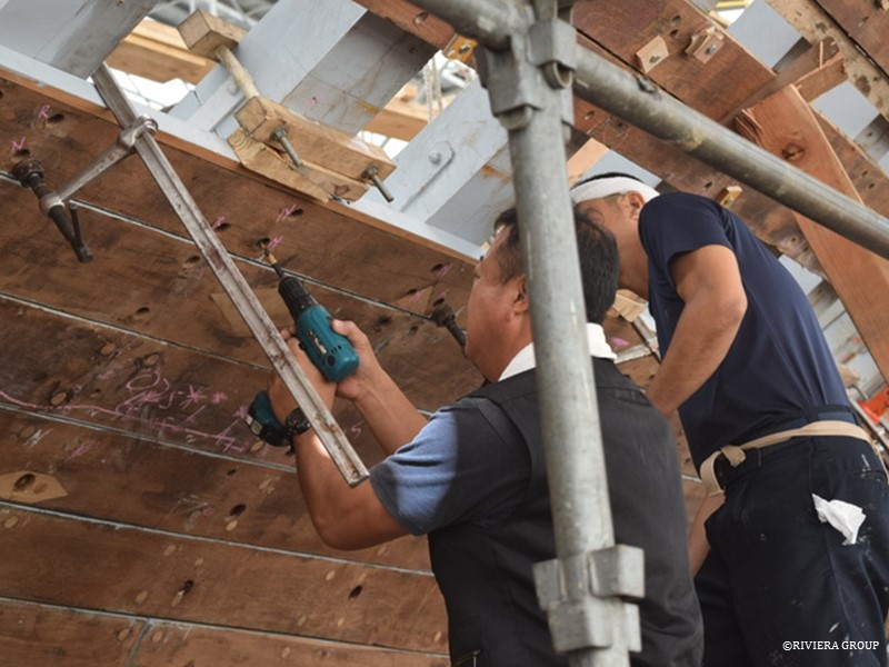
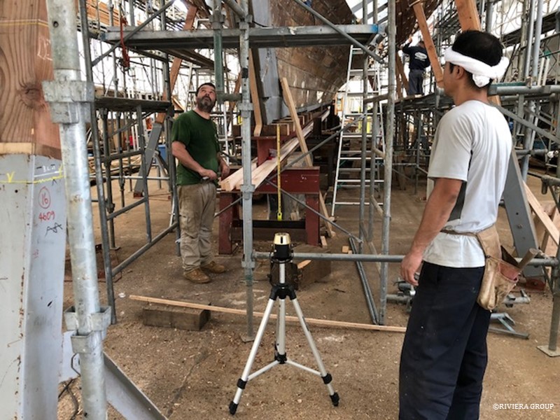
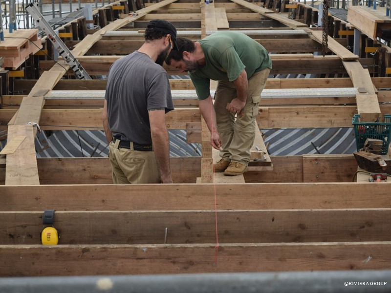
Graham Bailey, a highly skilled and talented Irish shipwright and experienced sailor has joined our team. Here he drills the holes through the frames that will take the copper rivets that hold the floors. The rivets will pass through the floor, the frame, and the plank—so great care is taken to miss any existing fasteners.
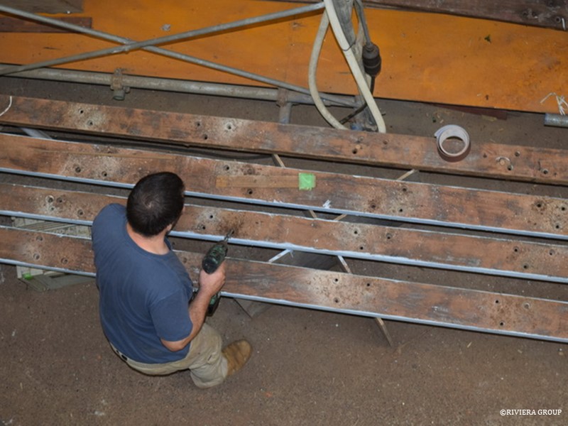
 

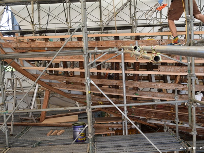
Before the planks are refastened, each existing hole needs attention. The hole must be clean and the counterbore that will take the bung must be clean, round and of a consistent size. If necessary, holes are bunged and re-drilled. Some holes may be filled and discarded completely. Each hole must be identified as to its purpose, whether it’s a dump or rivet. The copper rivets holding the hardware are larger than the naval brass rivets used to hold the planks so they need to be marked. Holes that have been bunged and repaired with graving pieces are re-drilled.
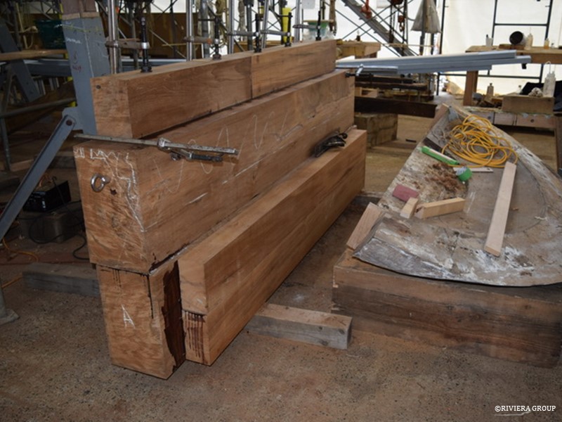
 

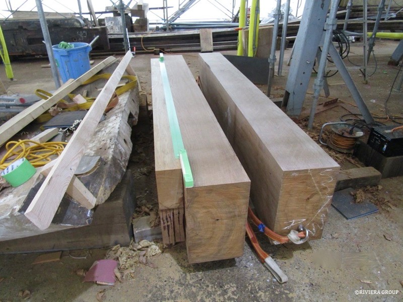
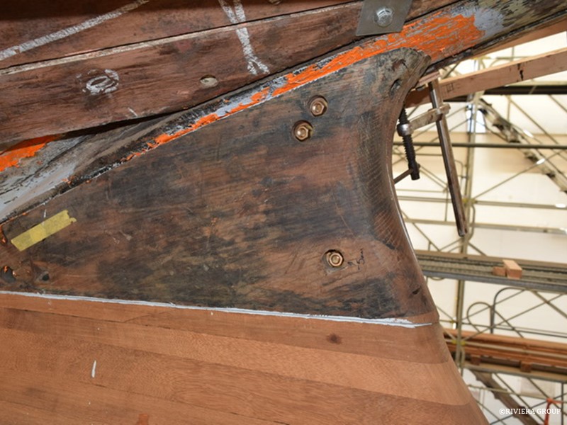
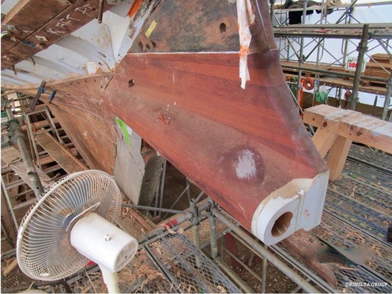
At the stern, the new chock is taking shape (above left) to replace the old one (right). Its weight is too much for one person, so a lifting ring is fitted at each end so that the pieces can be swung on a chain. Trying to keep waste to a minimum is a challenge. Although there are several pieces in this log, only one joint will be visible at the end in the same place as the original. The original stern chock (or archboard) was two pieces securely bolted together. Although we have used glue to bond the teak, bolts will be used again to secure the two main logs, as relying completely on glue for such an exposed and structural piece would be worrying.


Although the original chock looks to be in reasonable condition, it had some problems that were not practical to repair. Many cracks and splits emerged over the years and many local repairs were made. The area around the mortice that attaches the chock to the horn timber tenon had water ingress. So many repairs would have been necessary that it was decided to start fresh.
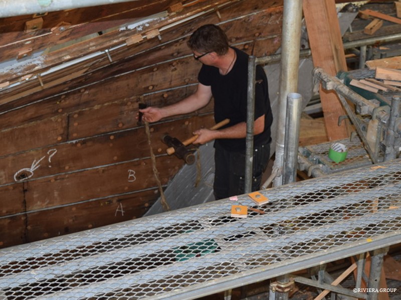
 

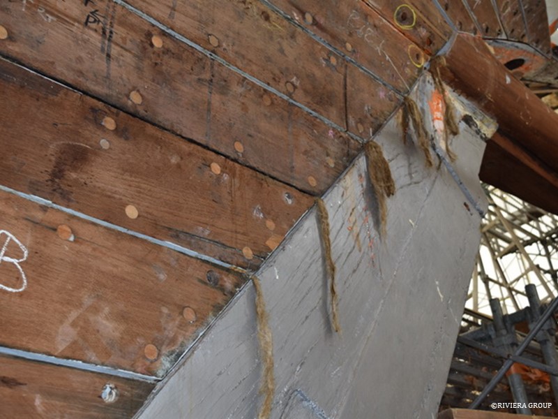
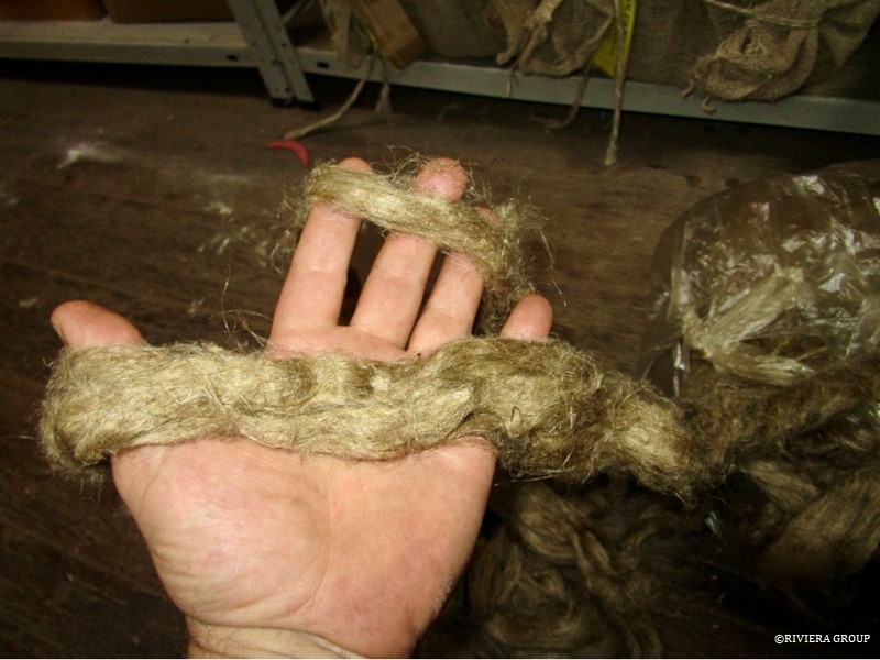
Jesper is doing some caulking at the stern (above and below). Although the planking is not finished the caulking process is started on some of the broad strakes at the stern and butt joints.


October 15-22 , 2018
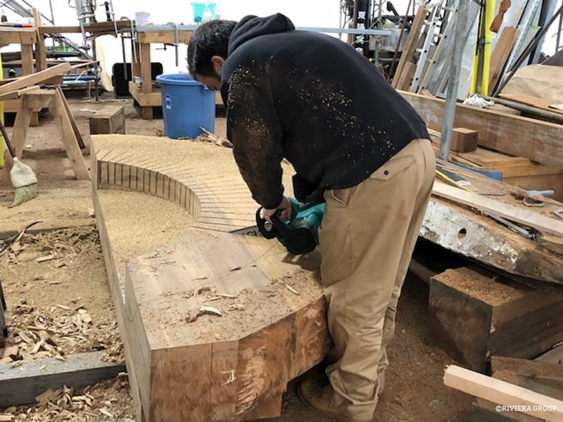
Paul has turned the stern chock over to cut away material and start the shaping process (above).  A chain saw is used to kerf waste material so it can be removed quickly.
 

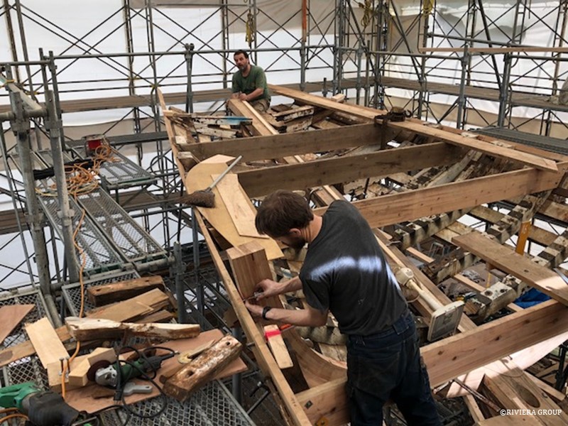
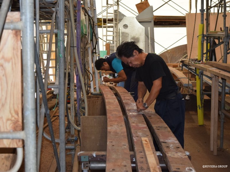
With Graham joining the planking team, the speed goes up a notch.
 

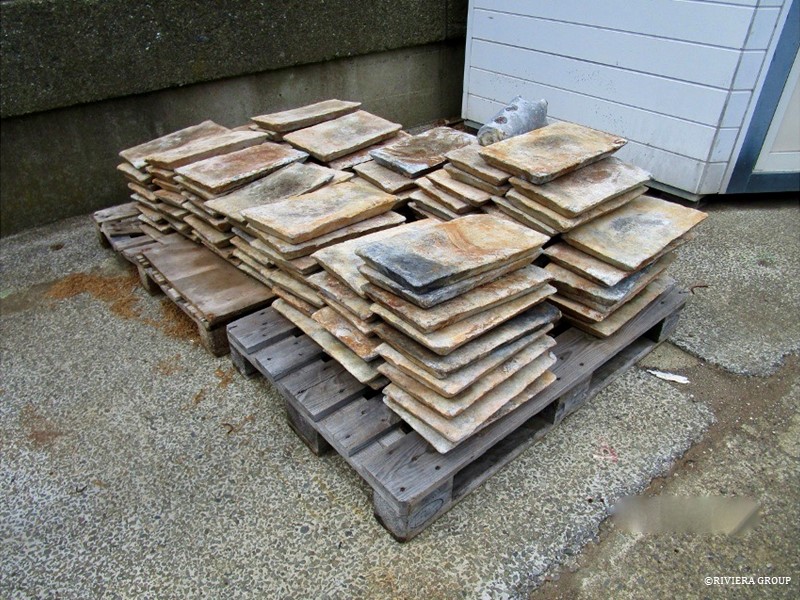
Makoto and masa have a system in place for plank repairs. Each plank is numbered and stacked in order. As each strake is fitted, the next set of planks are laid out and the necessary treatments are carried out. Each plank has its own unique issues and it’s a skill to identify each problem and come up with an effective and fast solution.
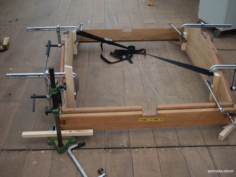
 

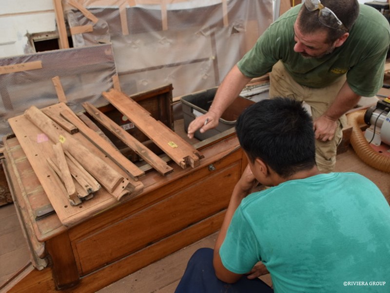
Work on the deck furniture is moving forward as original deck hatches and skylights start to be re-assembled. The passageway skylight (above) is held with clamps to keep it square. Wet varnish, red lead and linseed oil putty is used in the joints. A 3/8-inch Naval brass rod will be driven down through the dovetail joints to keep them from separating.
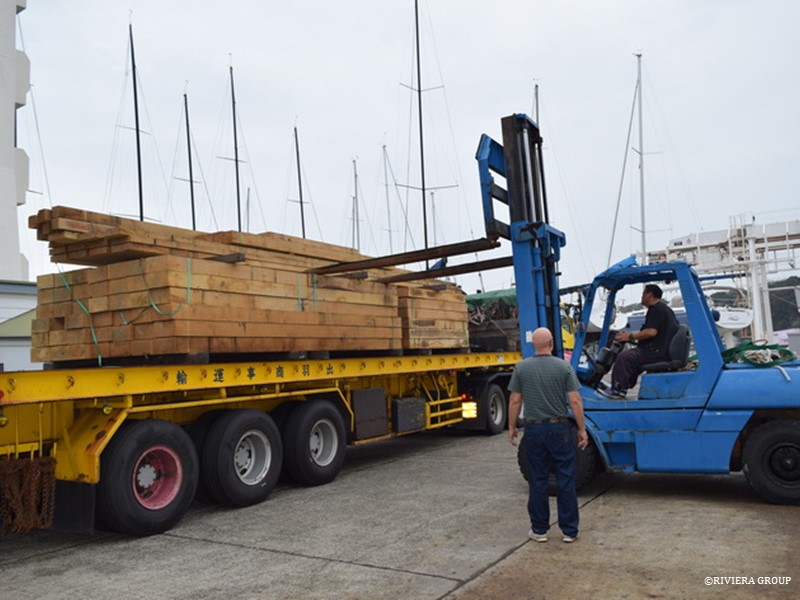
 

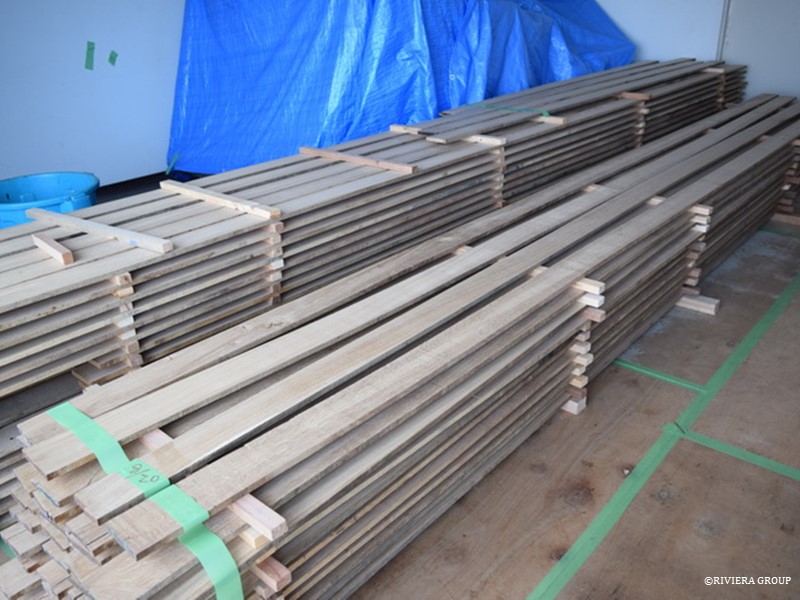
Fresh oak arrives from the UK to replenish our fast diminishing stock. The amount of lumber that goes into restorations is always surprising.


October 22-29 , 2018
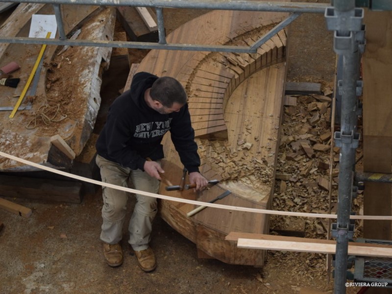
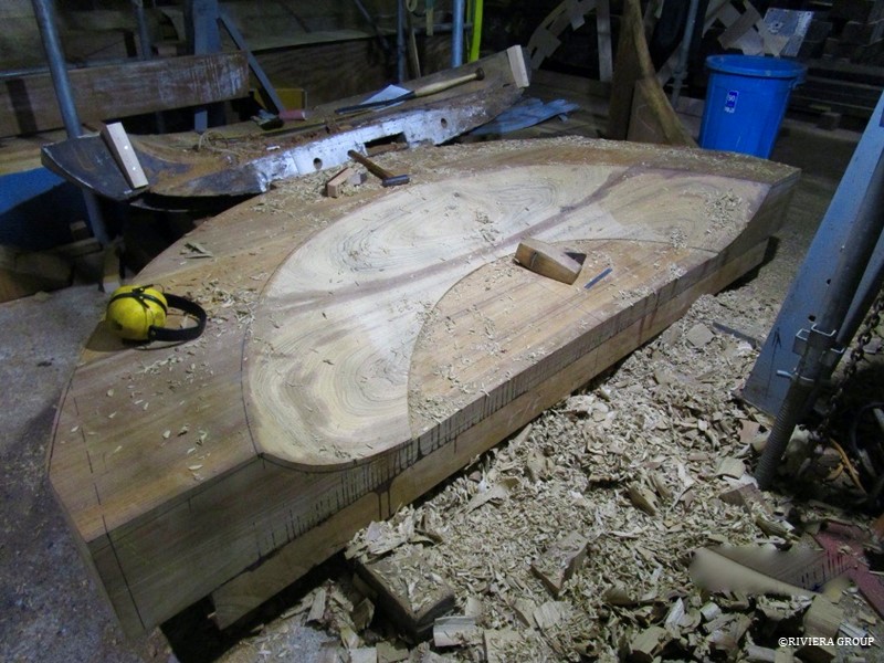
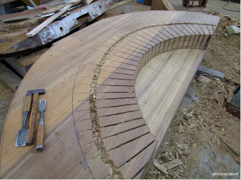
Paul at work on the stern chock (above and below).
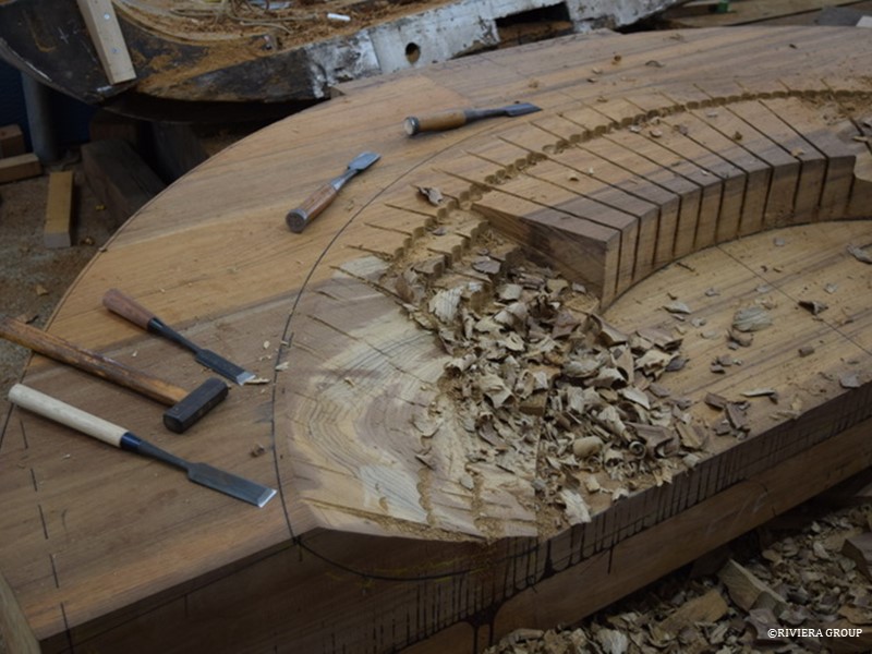


The lowest curved section (with the wooden plane lying on top) will be at the finished deck height. At the top of the gentle slope up is where the taffrail will sweep around the back of the boat. The brown oxidized line through the middle of the of the freshly cut timber shows the joint between the two logs that will be visible in the finished piece. Freshly cut teak is pale compared to older exposed surfaces and will quickly get darker when left to the air. It does help show the grain in these pieces nicely.
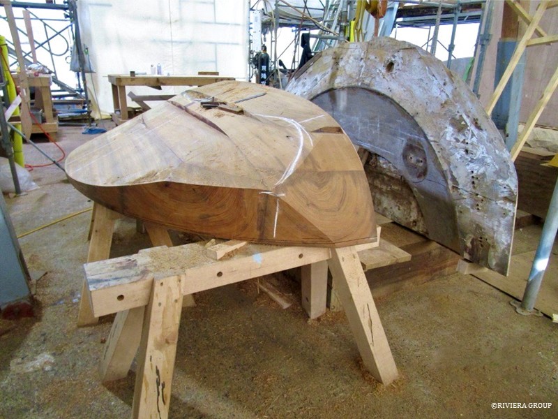
 

The chock is flipped and more material is removed from the back. It gets lighter everyday but it is still a weighty piece. The old chock stands by.
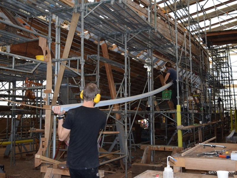
 

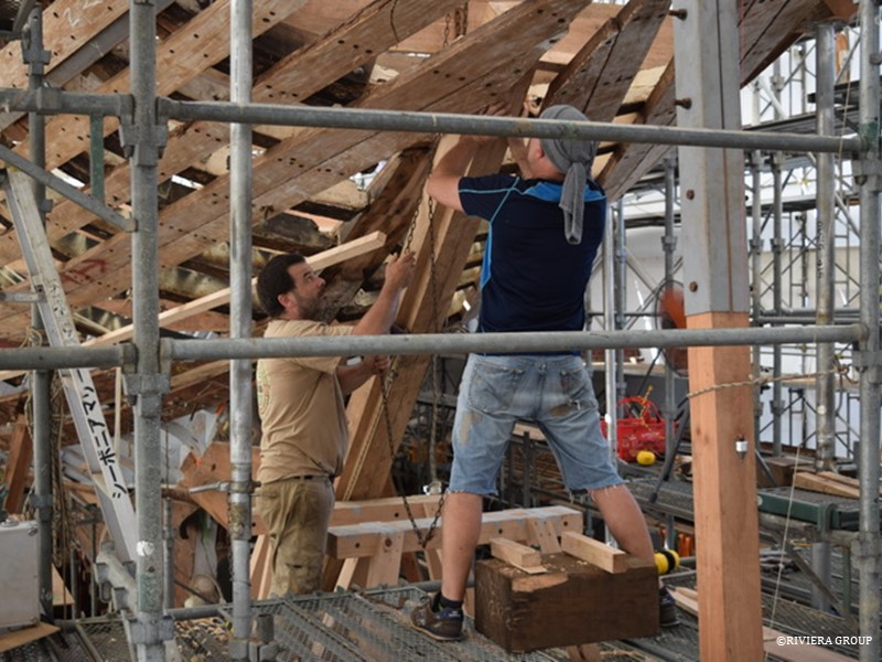
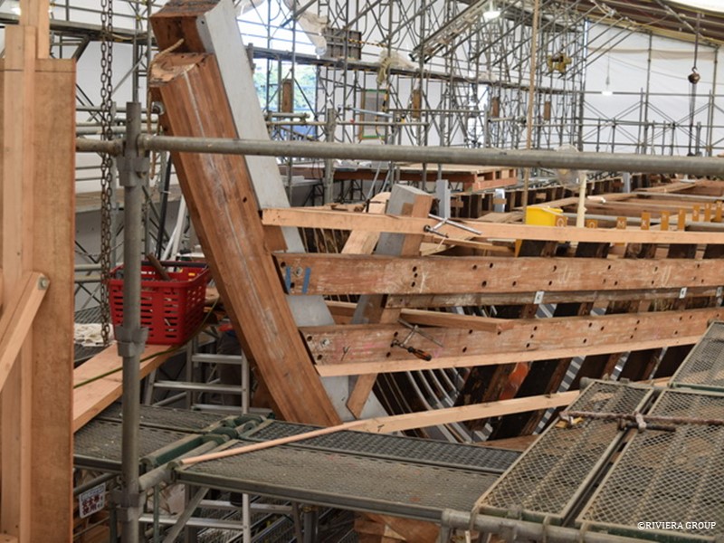
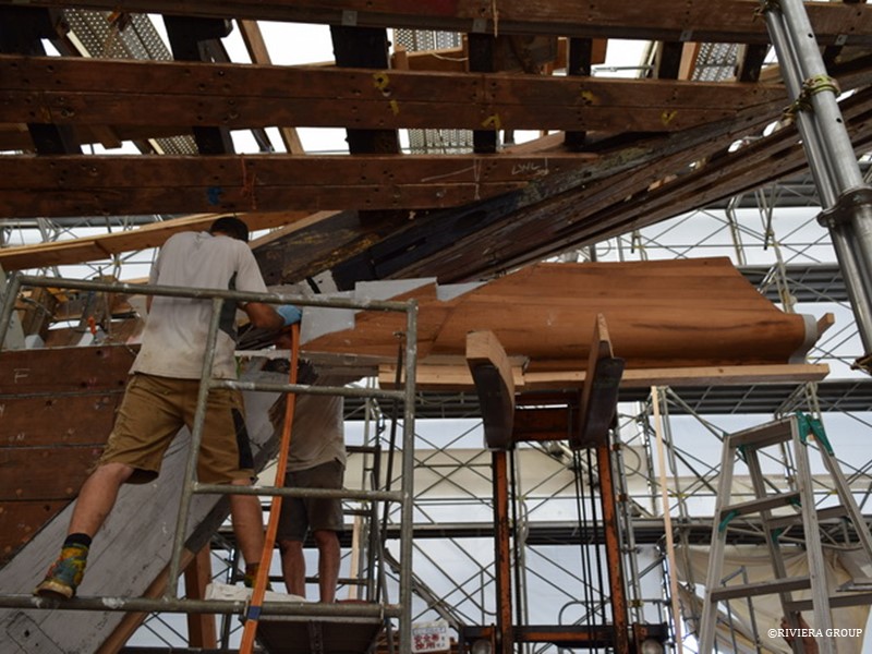
Mattis (foreground) and Graham thread a plank through the scaffold.


Follow Us

Restoration by RIVIERA GROUP

Restoration photos by Yoichi Yabe & RIVIERA GROUP

Text and photographs copyright © 2019
RIVIERA CO., LTD. All rights reserved.
Email : pr@riviera.co.jp

Blog — September , 2018

Blog — September , 2018

September 10-17, 2018

Some of the approximately 5 tons of lead ballast (above) that was removed from Cynara’s bilge. Internal ballast would be redistributed later to account for the new systems, the tanks and machinery layout.


As the planking work makes its way up the hull, the scaffold has made the work easier. There is a patter in the planking: each plank has two dumps and one rivet at each frame pair. The pattern is arranged so that the rivets are placed alternatively on the forward and after frames, and top and bottom of the plank. Each rivet is also arranged so that it alternately passes through the forward and after futtock in the vertical direction as well. If that sounds confusing, it is, especially when we use existing holes.


The oak transoms are now finished and fitted to the new horn timber section and primed. They still need final fairing into the hull and deck, but now the after end of the ship starts to take shape.


The new horn timber section (above) is housed into a temporary pine log to hold everything, including the ends of the ribbands, in position. Several of the single frames can be seen poking above the sheer line.


The new stern tube has been fitted and the alignment of the engine beds can begin.


This section of galley skylight hatch (above) has been veneered on its inside face. Deep scarring and scratches were revealed when the paint was removed. Although some patina is desirable in a historic vessel restoration, ugly scarring and damage from previously careless work is not. The piece was rendered unvarnishable (which is probably why it was painted) but we’ve cleaned the surface and used a teak veneer to cover the damaged surface. The hatch itself is still original but the interior will look clean and fresh under the varnish.


September 17-23 , 2018

Laminates for the deck beams are accumulating in our mini-kiln. It takes several weeks to produce useful laminates.
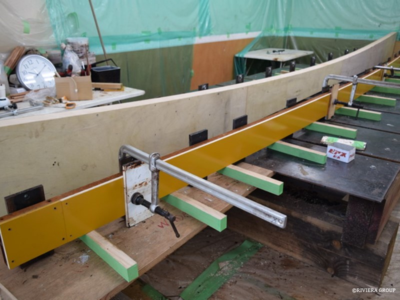
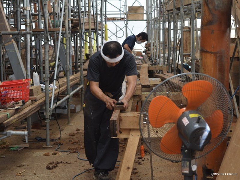
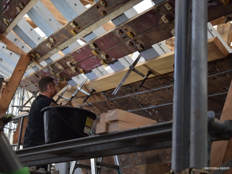
 

A deck camber gauge has been made in plywood (above) to show the shape of the deck beams. The crown of the deck is about 6 inches over approximately 18 feet. That sounds like a lot but that’s the way it was drawn by Nicholson and after the beams are fitted, the proportions will look right with the size of the ship. The old deck beams couldn’t be used because their shape was distorted over the years.


Kawashima is fairing a plank edge. We refair the planks before they are refitted because the caulking process can create a groove and raise points in the edge of the plank. Sometimes a few millimeters are lost, so a new edge is glued onto alternate planks to avoid accumulated error. On some planks it’s easier to take 15mm off and glue a new edge on.


Paul is fitting a plank of new wood. Despite most of the planking being in reasonable condition, there were a few spots where there was a need for new wood. Cynara was built in accordance with Lloyds of London rules, which dictates the size of timbers, types of materials, size of fasteners, etc., for different classes of ships. Cynara is classified as Lloyds A1, which has rules about where the butt joints in the planks are situated. We’ve made sure that the butt joint’s locations follow the correct patter, which is two frames between each butt joint and three planks between each joint on the same frame. This is a factor in whether to replace an entire plank or not. It also leaves a pleasing pattern but these will eventually be invisible after the plank seams are splined.


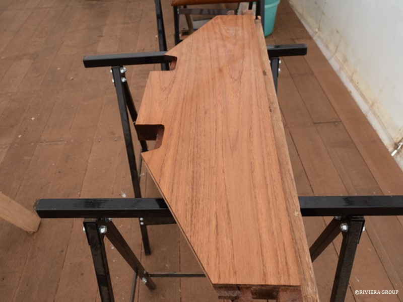
Teak pieces have been cut and laid out for Paul to begin work on the stern chock. Smaller pieces are glued together to make up the full depth of the chock. Most of the wood will eventually be cut away as the complicated shape of the chock has no straight edges at all.

Follow Us

Restoration by RIVIERA GROUP

Restoration photos by Yoichi Yabe & RIVIERA GROUP

Text and photographs copyright © 2019
RIVIERA CO., LTD. All rights reserved.
Email : pr@riviera.co.jp

Blog — August 27-September 2 , 2018

Blog — August 27-September 2 , 2018

August 27-Sep 2 , 2018

With the new horn timber section in place the transoms can now be fitted. Only the lower half of the transoms have been laminated at this stage, so these are being checked in their positions against the timber ribbands fitted on the hull.


A view from the tent scaffold at Cynara’s stern shows progress, with fresh and painted new timber standing out against the stained and blackened old wood.


In the joinery tent next door, the engine room companionway hatch is about to get its makeover. Paul and Hashimoto discuss the way forward.


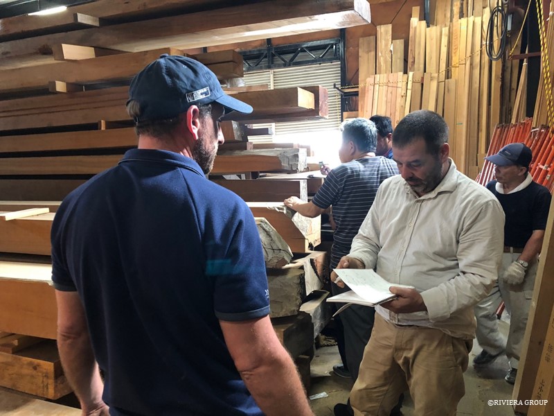
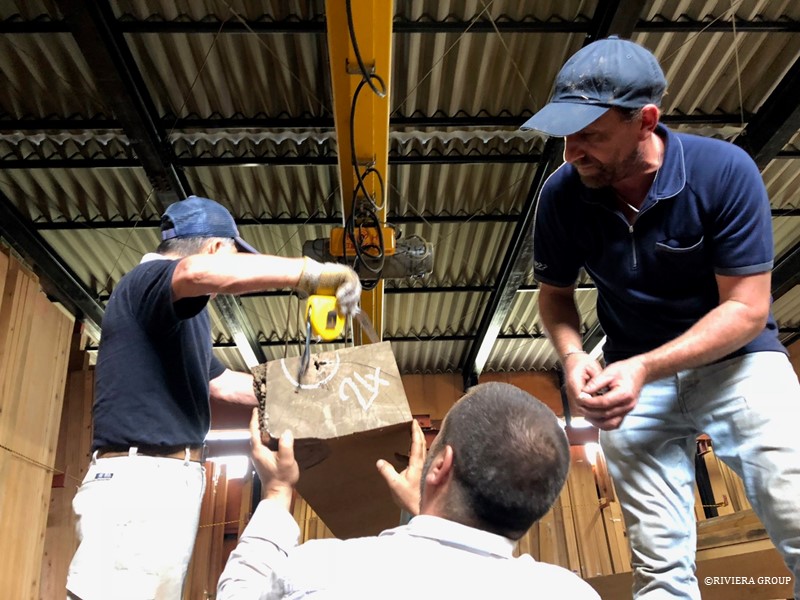
Paul and Ben on a visit to a lumber yard north of Tokyo, which had a good selection of teak. We take care to find pieces that can be most efficiently used, with the least amount of waste. Teak is rightly valuable (at least until new forests are planted) and this makes the selection stressful. We have to hope that there are no hidden defects hiding in the center of the purchased lumber, which will only be revealed after cutting.


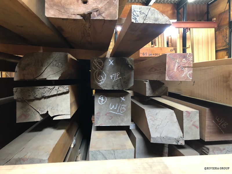
Each piece is marked with its hopeful final destination (above and below). We need timber for washstrakes, capping rails, and coverboards and all require clean, long lengths. The perfect tree is impossible to find and defects in the timber are inevitable. We mark the defects and hope that we can work around them with careful planning.

Follow Us

Restoration by RIVIERA GROUP

Restoration photos by Yoichi Yabe & RIVIERA GROUP

Text and photographs copyright © 2019
RIVIERA CO., LTD. All rights reserved.
Email : pr@riviera.co.jp

Blog — August 13-19 , 2018

Blog — August 13-19 , 2018

August 13-19 , 2018

Richard makes minor adjustments to one of the housings or ‘boxes’ in the new stem section that will take the new frame foot.


Mattis starts to fit single frames in the counter stern. It’s difficult to see here but the centerpiece of the hull in the stern (the horning timber) has been removed and will be replaced. The end of the timber was distorted and had defects that had not stood the test of time, so the aftermost half was removed and a new piece attached with a large scarph joint.


Paul and pascal feed the new horn timber section up between the planks through the open centerline in the counter stern for a test fit. If the horn timber is not centered correctly the entire stern and anything built here in the future will be off-center.


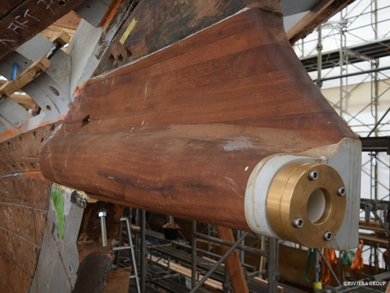
An infill piece above the shaft log fills the space above the shaft log and conceals the rudder tube that passes down through it. It completes the skeg section that is the top part of the rudder assembly. With Cynara’s unusual offset propeller shaft arrangement, the top third of the rudder is fixed and the rudder operates below the shaft exit.


Cynara’s rudder swings below the shaft log (above), which places the propeller after the rudder.


With the stem now in place, plank lines have to be set to ensure that the deck line remains true to the drawing, and the original planks can now be refitted in the same position they were in before removal.


Now that the lines have been checked and established in the bow section, Ben fits the four short single frames closes to the stem head. These are the smallest frames on the boat.


The stem head is waiting to accommodate the future bulwarks and bowsprit.

Follow Us

Restoration by RIVIERA GROUP

Restoration photos by Yoichi Yabe & RIVIERA GROUP

Text and photographs copyright © 2019
RIVIERA CO., LTD. All rights reserved.
Email : pr@riviera.co.jp

Blog — August 1-5 , 2018

Blog — August 1-5 , 2018

August 1-5 , 2018

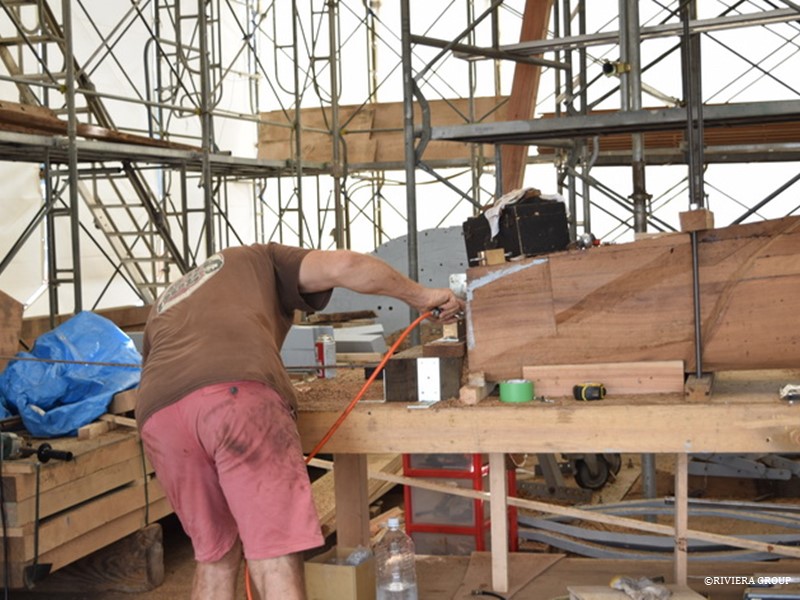
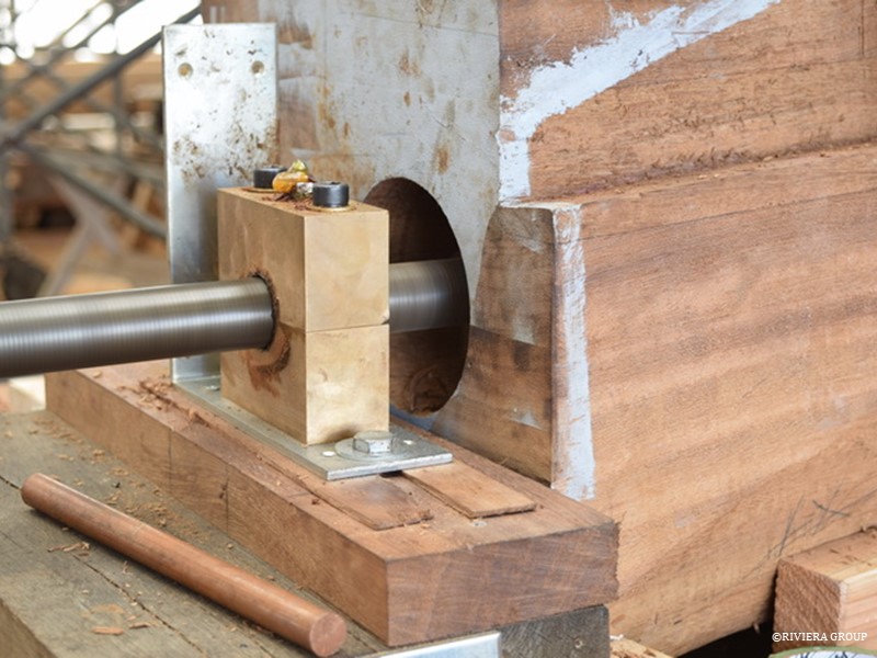
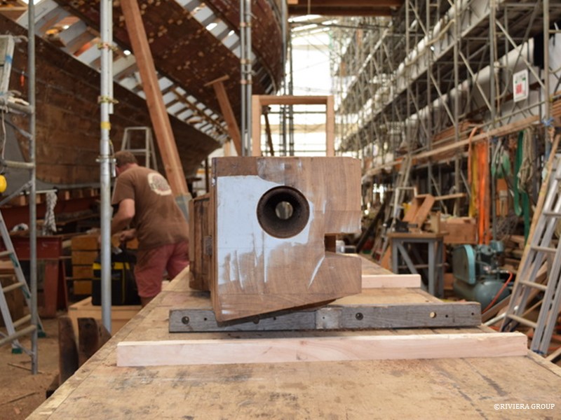
Lewis’s shaft boring project is progressing steadily. A pilot hole has been drilled and now the boring bar is set up to cut progressively larger diameters at an oblique angle through the chock.


An electric drill drives the cutter as a brass bearing surface at each end (above) keeps the bar steady. One end of the bar has a fine pipe thread which keeps the cutter moving steadily through the threaded bearing at an even pace.


The final hole diameter (above) was reached after several passes.


The shaft log was then dry fitted in a final alignment check.


With the shaft log in place, the center of the rudder has to be found using the center of the stern post that carries the rudder and a centerline on the deck.


We used fishing line and plumb bobs to check the rudder position from the deck center.


Follow Us

Restoration by RIVIERA GROUP

Restoration photos by Yoichi Yabe & RIVIERA GROUP

Text and photographs copyright © 2019
RIVIERA CO., LTD. All rights reserved.
Email : pr@riviera.co.jp