March 1-8
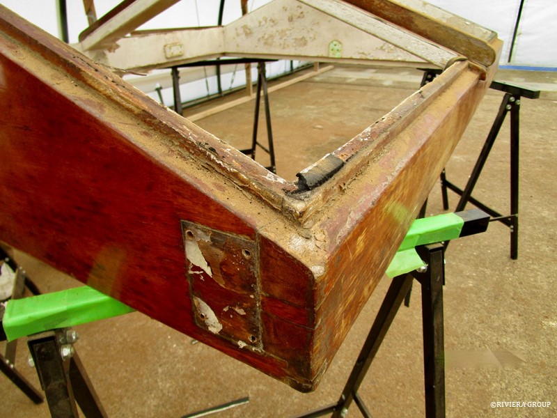
The teak skylight of the main saloon looks battered and worn but after a closer inspection the piece is not in bad condition considering its age. This was true for all of the deck skylights, hatches and companionways. This is a testament to both teak, as a durable timber, and the construction methods at Camper & Nicholsons in the 1920’s. As we’ve said before, nothing was glued during the construction of Cynara. This means furniture can be carefully deconstructed and individual components cleaned and repaired, where necessary, and then reassembled.
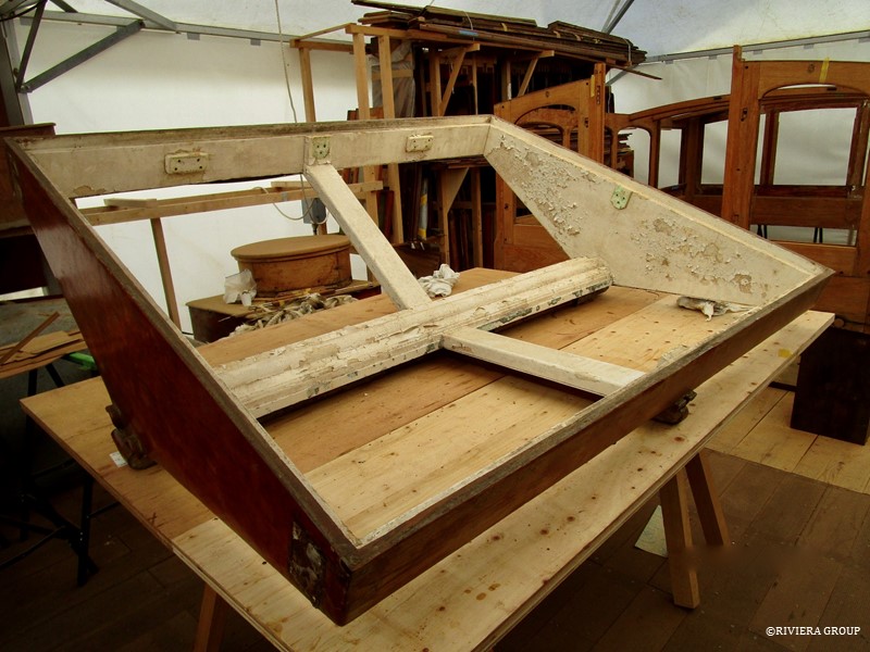
The interior of the main saloon skylight had several coats of peeling white paint which would need to be stripped to reveal the glorious teak beneath.
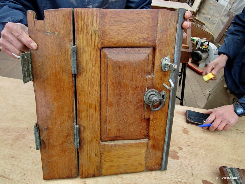
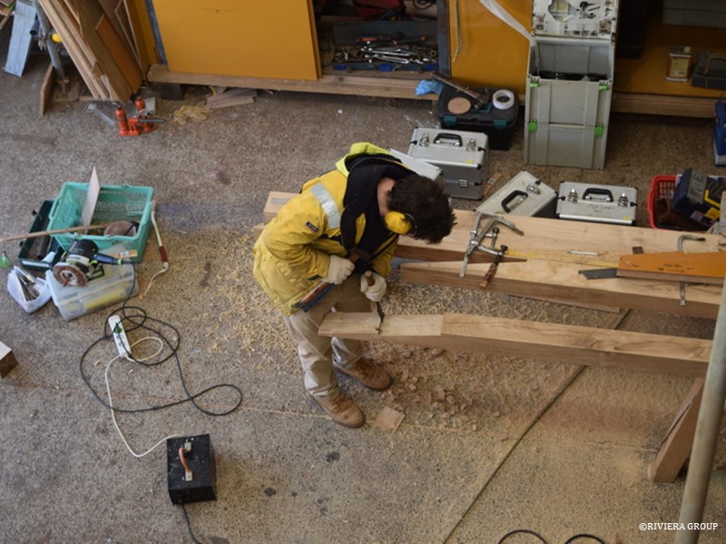
One of the doors of the engine room companionway. Here, over-sanding can clearly be seen, especially around the edge of the raised panel in the door. The sharp edges and detail have been rubbed away by over enthusiastic sanders of the past. The frame will be saved but the panel will be replaced. All of the hardware will also be salvaged, cleaned, polished and refitted.
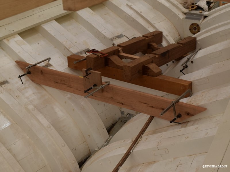
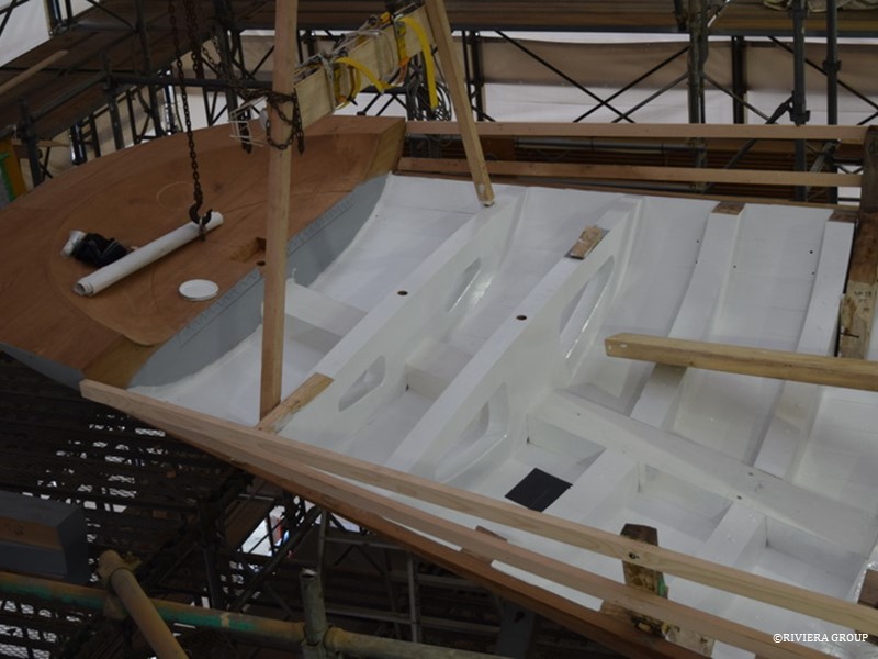
The new engine mounts are being tested. A temporary beam is fitted to carry a string line to the propeller shaft center. The propeller shaft is angled so that it misses the rudder tube by around an inch. This means the propeller shaft emerges from the stern post offset to the portside and passes through a faired wooden protrusion called a prop-shaft “log” above the rudder.
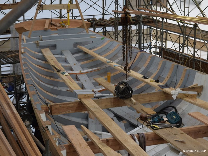
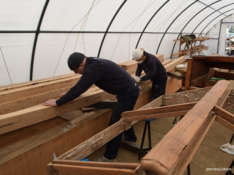
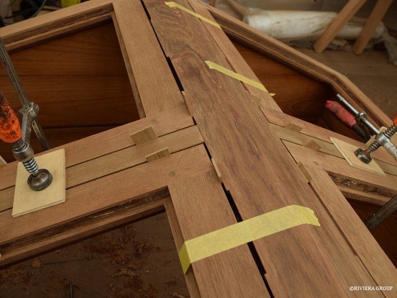
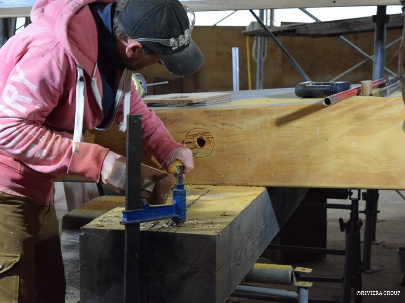
Deck preparation is well underway. The sheer clamps that will run the full length of the ship and are part of the support for the deck beam ends, both port and starboard, are laid across the temporary thwarts before fitting. These are a stout 9 ½ by 2 ½ inches (about 240mm x 65mm) of English oak but look deceptively small when laid inside the boat. The aft ends need to fit the extreme curves of the stern and so were steamed and twisted into shape before final fitting.
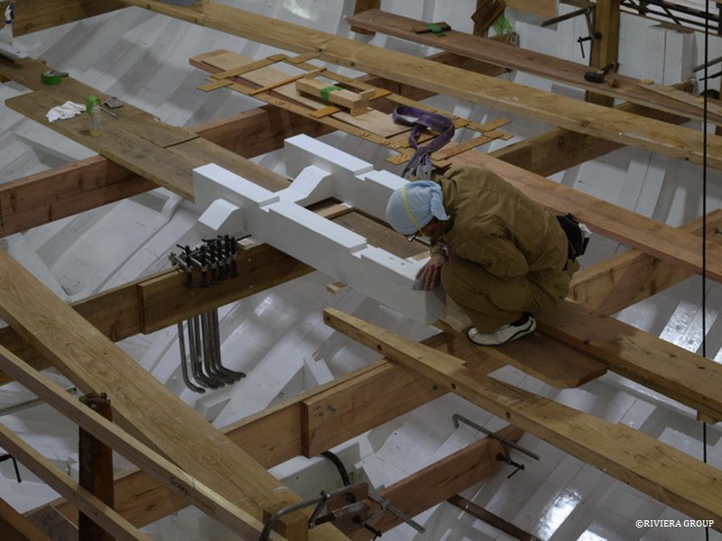
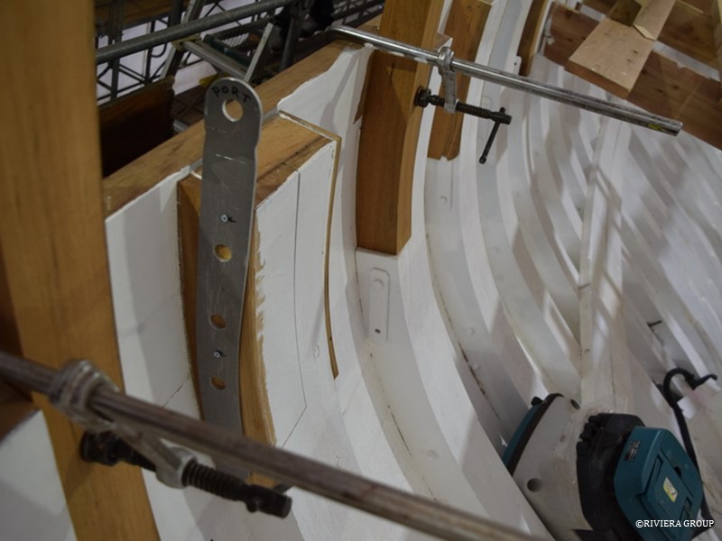
A plywood template has been fitted to check the size of the combined old and new sections of the web frame before the installation of the web frames around the main mast. At the main mast and further aft near midship, there is a galvanized steel web frame. This is a heavy steel structure that is bolted to the sides of the wood frames and extends up from the bilge and connects to the deck beams with gussets. This adds stiffness and helps take the loads of the mast and rig in this area. The whole web frame was made in individual pieces riveted together. The upper sections were re-galvanized and re-used but the lower sections in the bilge were replaced due to corrosion.
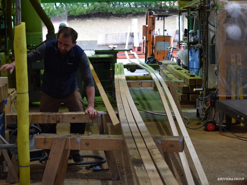
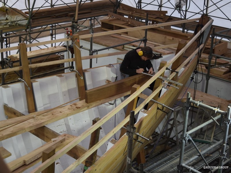
Ben struggles to find work space next to the batons being machined next to him. The pine batons snake through the entire machine shop and outside into the gardens beside the workshops. These will be used to find the positions of the stanchions fitted around the deck edge. They are made with pine sections scarphed together, creating batons that run the full length of the ship. Each one is then machined as one piece to make a long and fair baton.
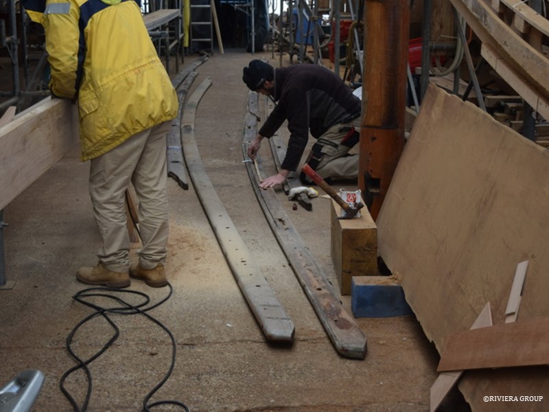
Nico uses the original capping rail to check stanchion spacing and position in preparation for fitting the stanchions. A new capping rail will be fitted to the stanchion tops but the old rail holds valuable information and is referred to for important measurements not available on our drawings.
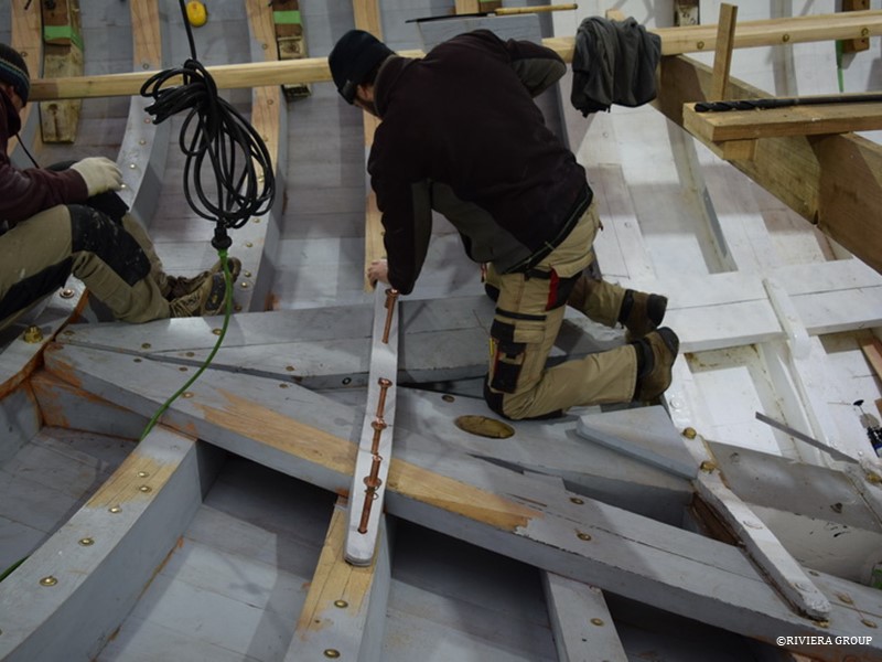
Nico drives 5/8 inch copper rivets home through an iron floor fitted just aft of the rudder. The hole for the rudder tube can be seen at Nico’s knee. The floor seen behind Nico, at his feet, is held to the horning timber with giant bronze lag bolts. Directly below is the rudder and propeller shaft and a through bolt is not possible.
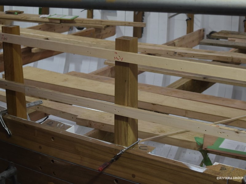
Here are the long batons in situ, with the original stanchions being used initially to set up the curve. Original C&N drawings, original wood stanchions and new drawings produced by Paul Spooner Design were used to find the final line. The deck edge, or sheerline, is important to find as a good line greatly enhances the overall look of a ship. This is also true for the top of the bulwarks where the capping rail will sit. Careful adjustment and a keen eye is required. Although many original drawings still existed (courtesy of the London Greenwich Maritime Museum) Paul Spooner played a vital role in checking, fairing, redrawing and providing missing information. When a line was settled on, measurements were sent to Paul Spooner, who checked them on his computer to confirm that the line was indeed fair.
Cynara’s length meant that the full length of the line could not be observed from stem to stern without changing viewing position, and a few millimeters here and there can make a big difference. Cynara also has a slight tumblehome in the bulwark which had almost been lost when she fell out of shape. With new calculations from Paul and carefully positioned original stanchions, all of the curves came together to find the ‘sweet spot’ that creates Cynara’s graceful sweeping lines. New wood stanchions can now be produced to replace the old, one by one, using the batons to show the correct heights and curves needed in the new teak stanchions.
Kawashima works on the crew companionway hatch. This is mostly original but new corner posts and door threshold are necessary. The old suffers from split and cracked mortice and tenons and fresh water ingress. This hatch sits on the foredeck and provides access for the crew to the crew quarters in the bow of the ship.
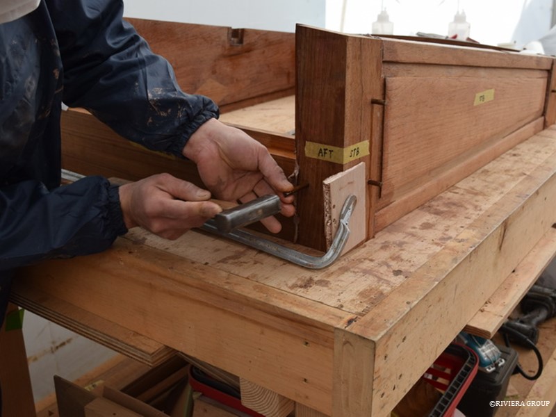
Kawashima is fitting the handmade teak dowels driven through the tenons of the joint. This is the exact same method C&N used to secure the joints in 1927.
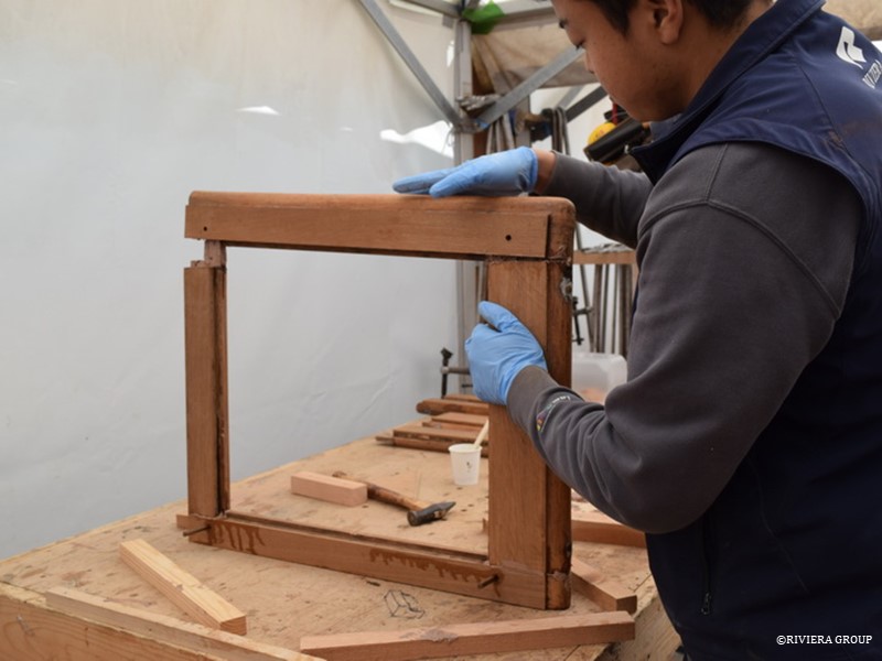
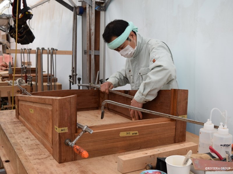
Hashimoto reassembles a window frame from the saloon skylight. Local repairs were made using epoxy but the mortice and tenon joints in the frame are secured with teak dowels and prepared with a compound made onsite that was almost identical to what was originally used. It’s always preferable to make local repairs invisible and that’s what the end goal is. We match the colour and grain of the original wood wherever possible. However, an invisible repair is not always achievable, but a repair that can be seen, if done well, can be considered an ‘honest’ repair and becomes part of the story of the piece.
March 11-18
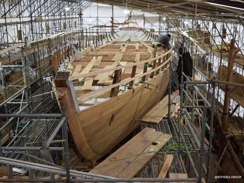
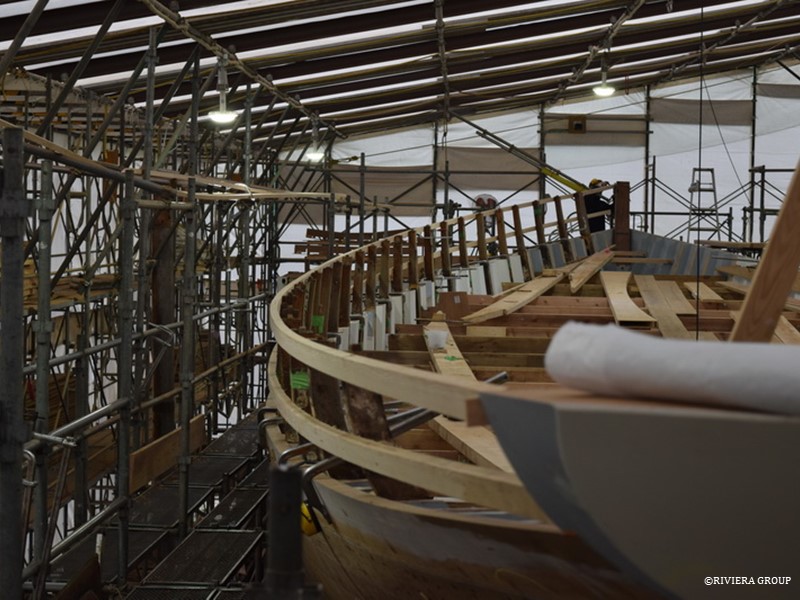
A view from the bow looking aft showing the spider’s web of scaffolding around Cynara. The starboard side sheerclamp is being fitted at the bow, and the top of the stem will eventually be cut down to accommodate the bowsprit.
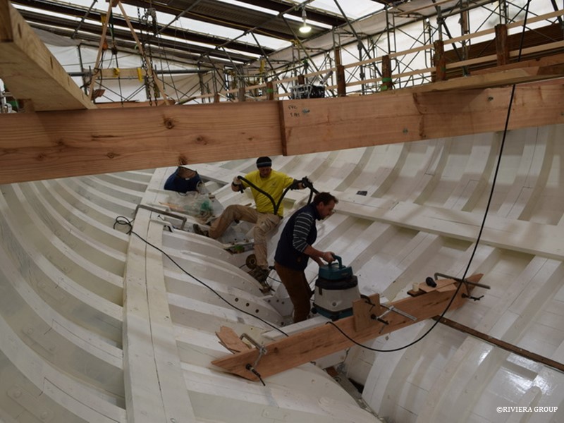
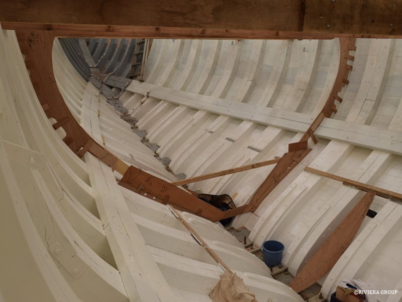
With the inside of the frames faired, the paint is touched up and good coat of bilge paint is applied from keel to deck. The position of the engine beds has been confirmed and now, with fresh paint applied, Ben and Richard prepare for a final fit. Before the engine beds are installed however, the last of the centerline bolts must be drilled and fitted here just under where the engine will eventually sit.
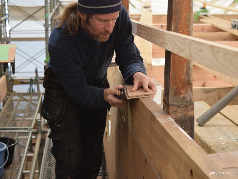
Graham works on the teak stanchions that will carry the bulwarks and capping rail. Using the old stanchions gives him a lot of information and provides a three-dimensional pattern to work with. Sometimes a stanchion may need to be adjusted to fit the desired line and here Graham produces a fine wedge to be inserted at the stanchion to adjust an angle. The new stanchion will be produced incorporating the adjustment.
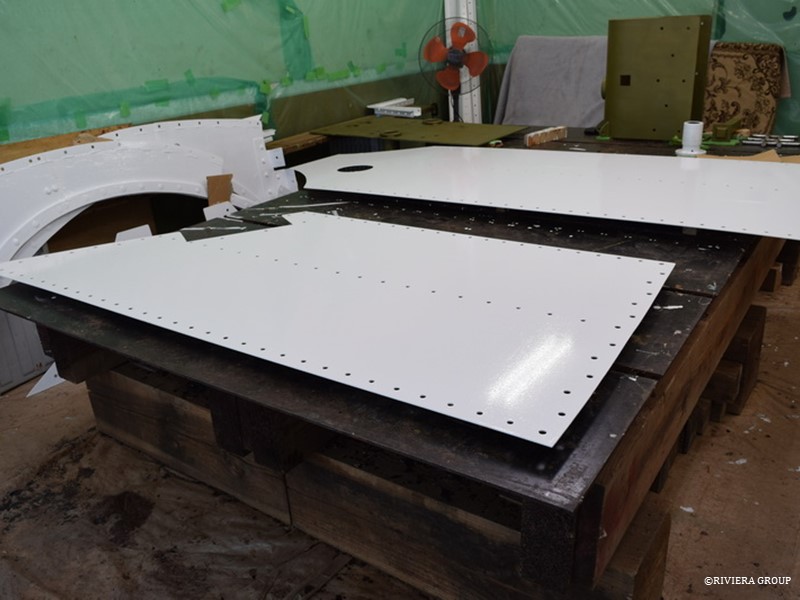
These galvanized steel panels will be bolted together to create the bulkhead that separates the engine room from the accommodation area. The original was riveted but for ease of construction, we elected to bolt the new bulkhead. A fresh coat of epoxy paint is applied before installation. In the background are parts of the web frames mentioned earlier, painted and ready for installation.
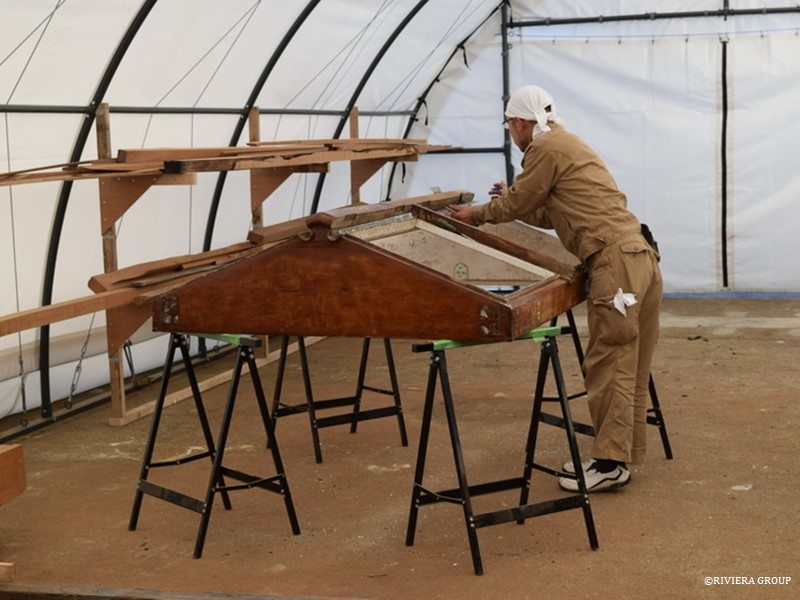
Kakimoto begins the stripping process by removing hinges and fittings. He works in an uncharacteristically clean tent. This is because the tent is newly constructed and will eventually be used for spars and rigging. But, before the riggers get started, we can make use of the valuable space it provides.
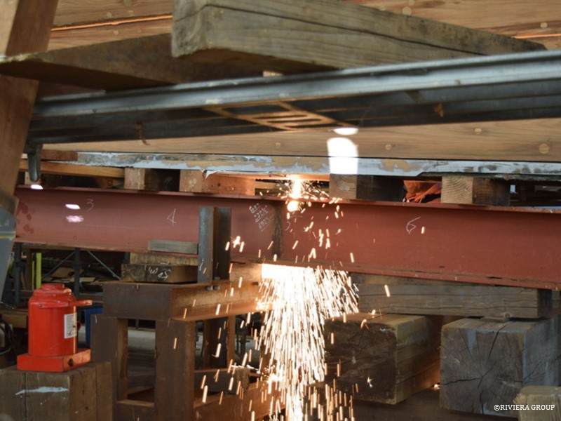
Seen here is the heavy H section girder, or strong-back, that used to support Cynara along the full length of her keel. With the ballast keel and the wooden false keel removed, a straight line is created, one of the few outside of the interior. This must be maintained throughout the restoration and the strong-back is used keep this line and support the weight of the ship. Now we are ready to refit the false keel. To fit the false keel, the after end of the strongback must be cut away.
Cynara had spent time in the Caribbean (and elsewhere), where ship worm is prevalent, so the original false keel was badly eaten. The wooden false keel is the lowest part of the ship and an easy target for the wood boring clam. Remedial work had been carried out and a protective stainless steel shoe had been retrofitted to the bottom, but the lower part of the false keel was too far gone. It was replaced with bilinga, an African hardwood, instead of the original English elm. The worm had also attacked the area around the rudder head where the rudder tube exits the hull.
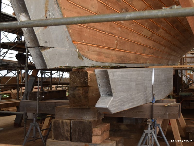
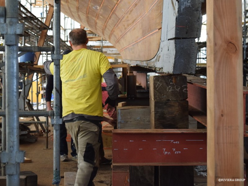
The after end of Cynara is supported with blocks in preparation. The false keel sits beside the blocks.
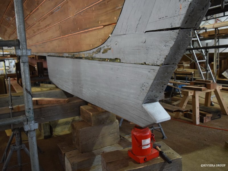
The false keel also carries the rudder. So its after end is shaped with a cove to suit the leading edge of the rudder and a rudder bearing that will be fitted at the base. Long naval brass bolts go through the false keel, keel and stern knee to secure the entire assembly. These bolts are directly under the engine and must be fitted prior to installing the engine.
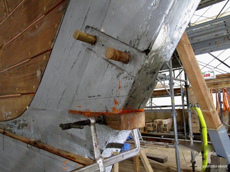
The end of the keel had shrunk, creating a gap between the stern post and the keel. A wedge is fitted being careful not to disturb the mortice and tenon joint connecting the two. Wooden bungs are used to close the holes left by the rivets that had previously secured the bronze rudder straps. New holes will be drilled when the straps are re-fitted. The oak stern post is original and although it had dried and shrunk dramatically, it is extremely hard timber and was retained.
Kakimoto applies a final coat of bilge paint before the engine beds are fitted for the final time.
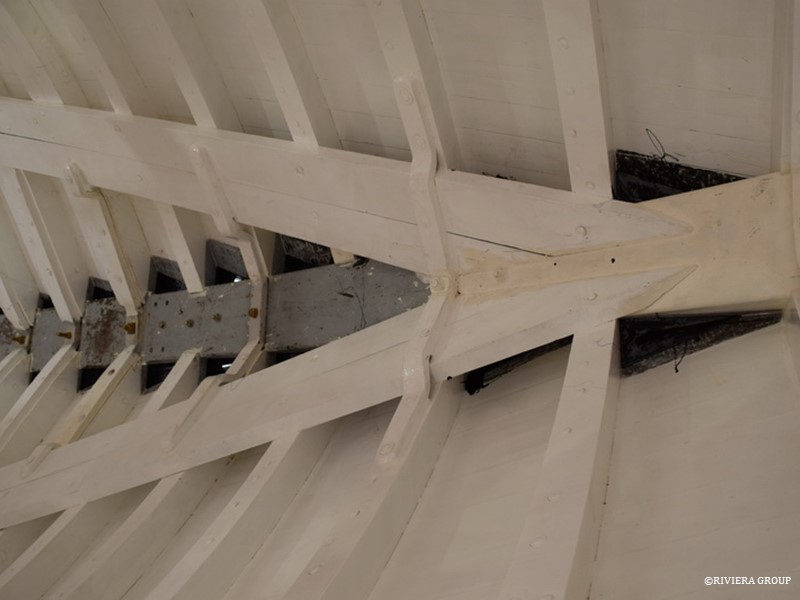
The stern area is beautifully finished. Here we see the transom frames which are hull frames and deck beams combined. The originals were cut from single pieces of oak but these are made up of separate laminated pieces bonded together. Fresh paint is applied throughout as Cynara moves to the next phase in the restoration.
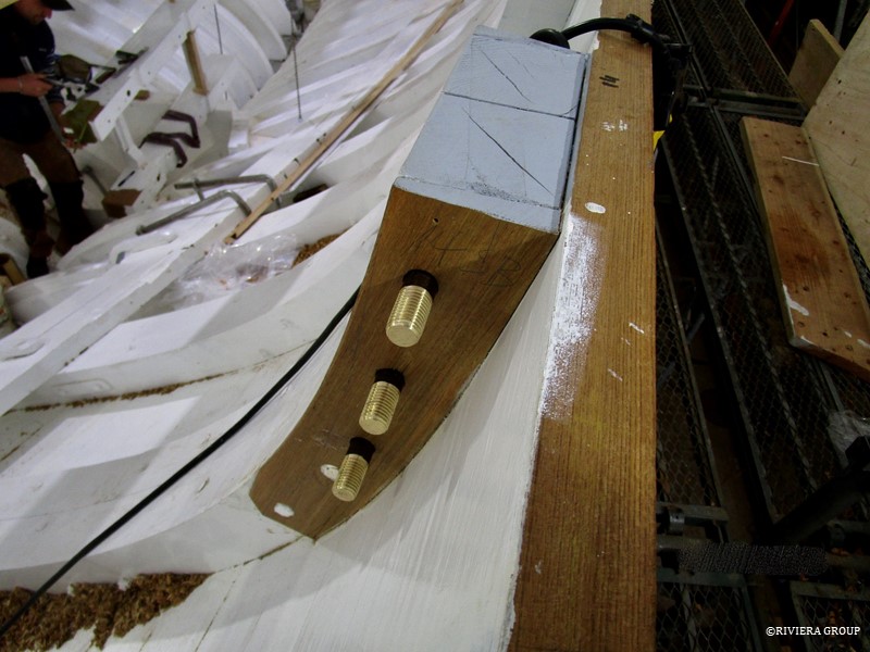
These are the mizzen mast chain plate bolts fitted through the frames. The original chain plate bolts were iron and the chain plates themselves were galvanized steel. The new bolts are in aluminium bronze and the chain plates will be stainless steel.
The first stanchions at the bow are of a larger dimension as they also form part of the chocks, or knights heads, that fill the space between the stanchion and the stem. This chock will be fitted with hawse pipes and is solid teak. Mattis works to get these important pieces fitted.
Two of the new teak stanchions in position.
March 18 – 28
Now that the sheer clamp is finished and ready to fit, Paul works on the beam shelf. Long lengths of English oak are scarphed together and will be riveted to the lower edge of the sheer clamp. The deck beam ends will be dovetailed into the sheer clamp while the lower edge of the deck beam will be housed into the shelf and riveted.
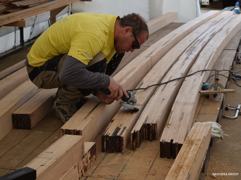
Pascal and Makoto sand one of the deck beams prior to painting. The beams will be finished to the undercoat stage before fitting, as waiting until later makes things much more difficult and time consuming. In the foreground is a skylight hatch stripped and ready to disassemble.
Freshly laminated deck beams ready for finishing.
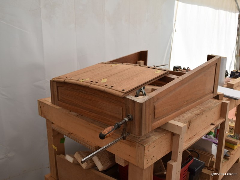
The crew companionway hatch has its original planking refitted.
With skylight frames reassembled the restored window frames can be measured. Shims and spacers ensure an even gap all around. The next step will be cutting hinges in and fitting new glass to the frames.
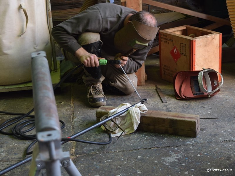
Richard welds a drill bit to a long steel rod to bore the holes needed for the false keel bolts.
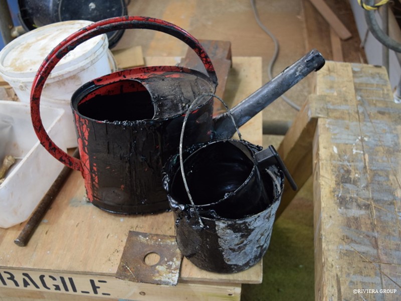
A watering can and an old steel bucket are ideal for pouring the melted bitumen tar into the water traps created by the frame-keel junctions. The low points along the keel that would trap water are filled with the tar so that any water finding its way into the bilge will not pond anywhere, but can run freely down to the lowest point where the bilge pumps will be situated.
Here we see the tar levelling the low spots either side of the stem in the bow.
Ben cuts one of the counterbores to receive the keel bolt nuts that will secure the false keel.
An exact aluminium pattern of the chain plates was used to decide the positions for the chainplate bolts in the frames. The chain plates must be orientated so that the head of the chain plate is in the correct final position at deck level to receive the turnbuckles that will tension the rigging.
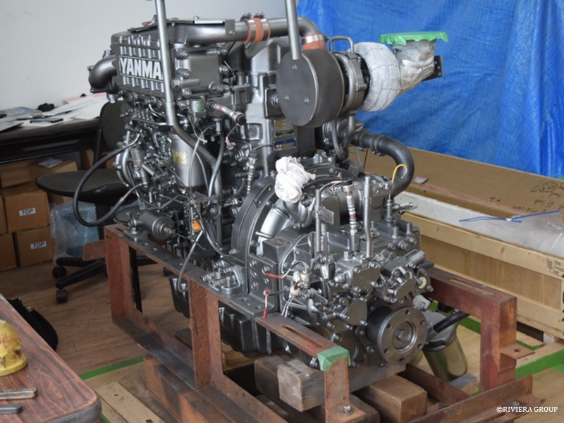
The freshly painted and reconditioned engine awaits installation.
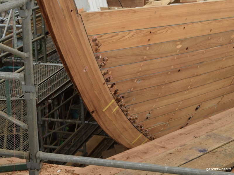
Bungs are fitted over the screws in the hoodends of the planking at the bow. Although the majority of the bungs have been fitted and faired, more riveting through the planks will be needed to fit the beamshelf, clamp and hanging knees. The old teak decking was not wasted; it was used to make the several thousand bungs we needed.
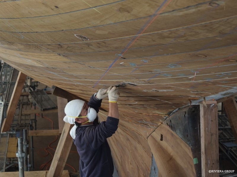
Each bung must be cut and faired flush with the planking.
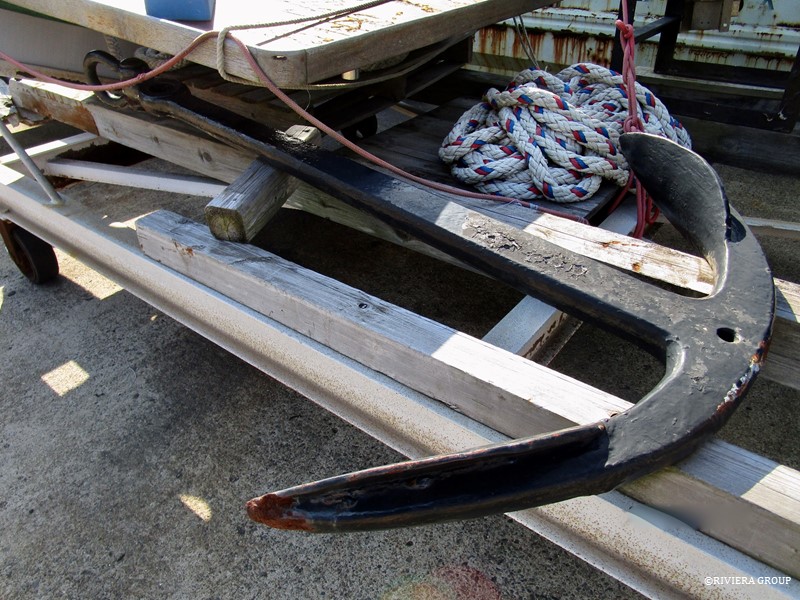
One of a pair of original iron anchors from Cynara. These will be cleaned, re-galvanized and re-used. The original admiralty marks can be seen under the many layers of old paint. We ordered two new anchors, but when they arrived, one glance told us the workmanship of the originals was much better, so we changed our plans and rebuilt the old ones.
Follow Us

Restoration by RIVIERA GROUP
Restoration photos by Yoichi Yabe & RIVIERA GROUP
Text and photographs copyright © 2019
RIVIERA CO., LTD. All rights reserved.
Email : pr@riviera.co.jp