Blog — March 26-30, 2018

Blog — March 26-30, 2018

March 26-30,2018

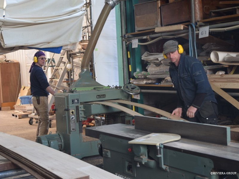
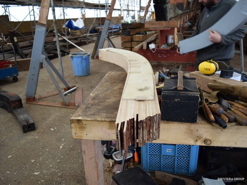
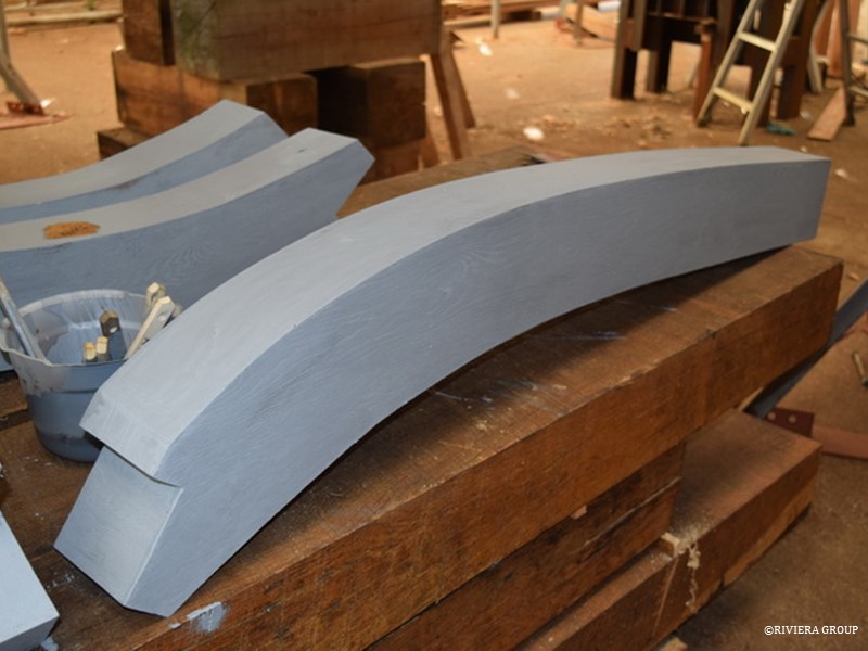
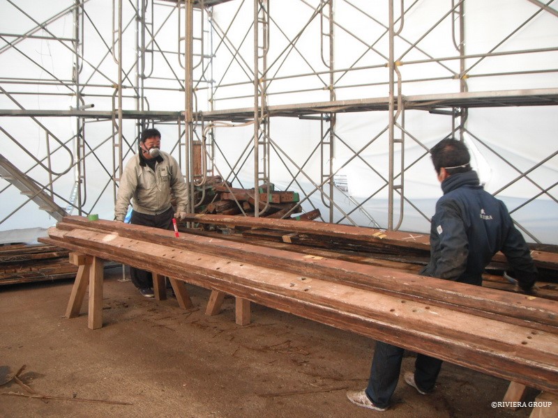
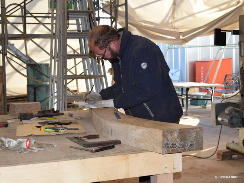
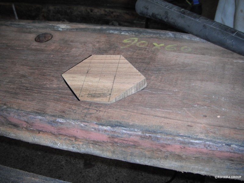
Once the deck beam laminates were sufficiently dry, they could be machined to size before being set aside to rest the exposed fresh timber. These (above) are almost ready to laminate. The laminates have to be dry before final machining to get them within the glue tolerances.


Producing the first futtocks took time, but Nico now has the process down to an art, and they take shape quickly.


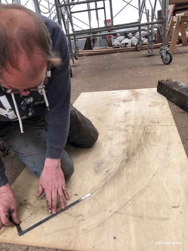
Lewis makes a plywood pattern to check the frame against the ribbands.


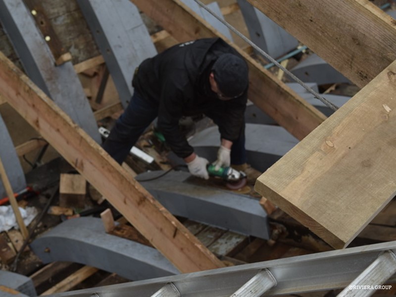
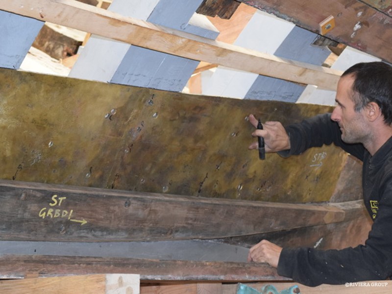
A final check of the alloy plate (above) before the rebate is cut in the backs of the frames (below).


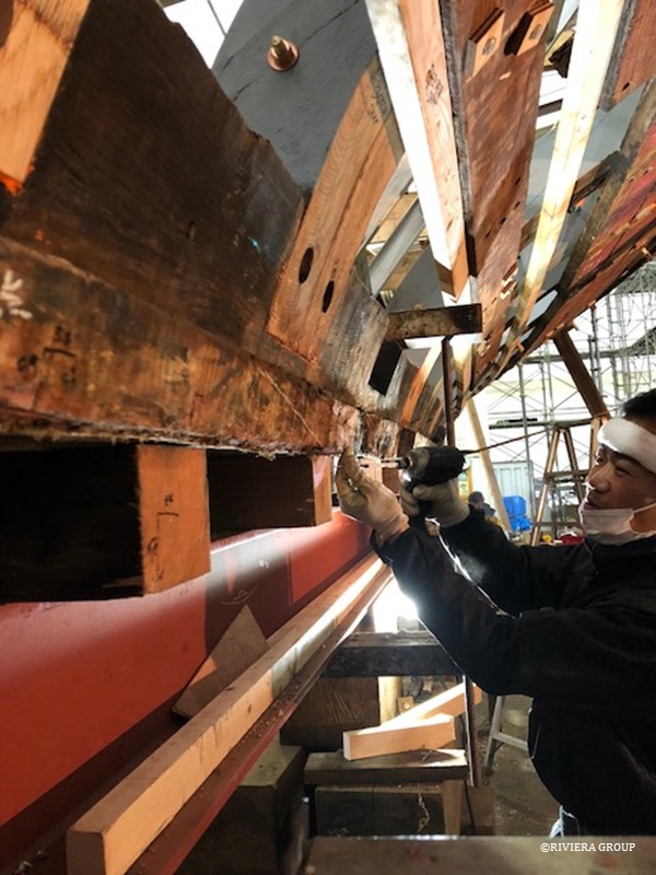
The plate is bedded in on copious amounts of red lead putty that we made onsite from raw ingredients.


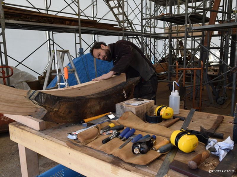
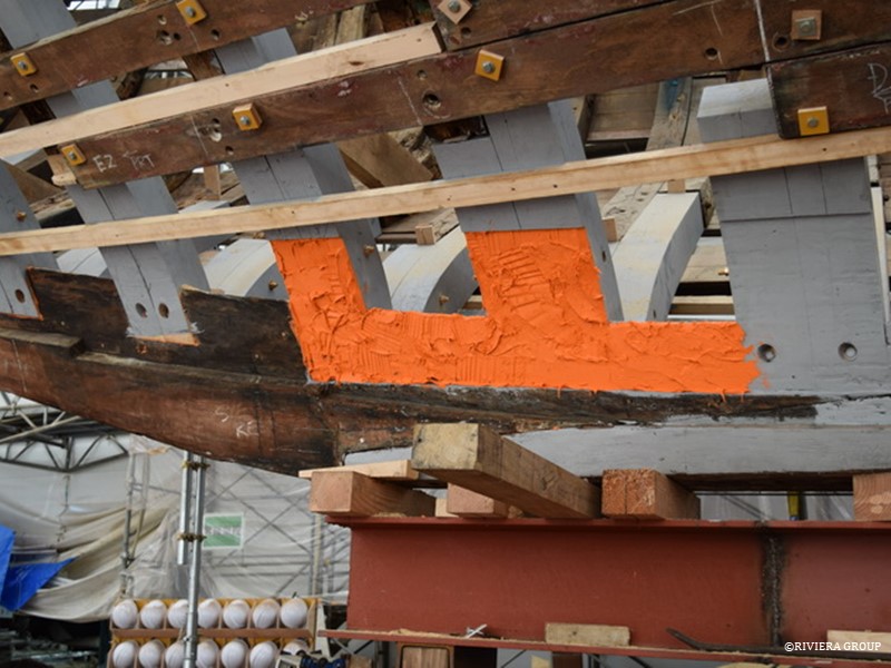
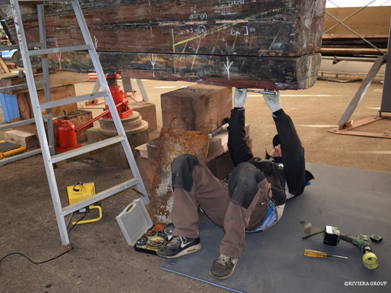
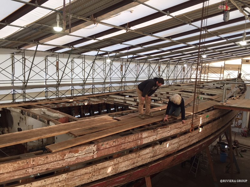
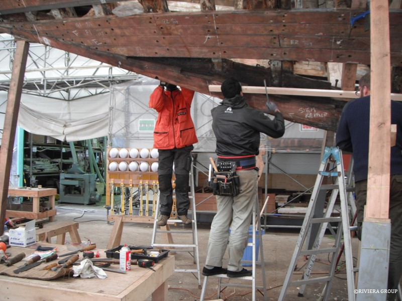
The site of Kawashima’s keel repair is ready for glue. The strange shape is due to its location adjacent to the scarph joint in the keel timber. We didn’t want to blue a patch over the joint.


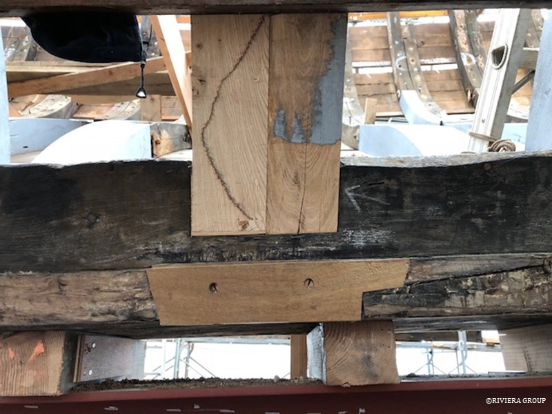
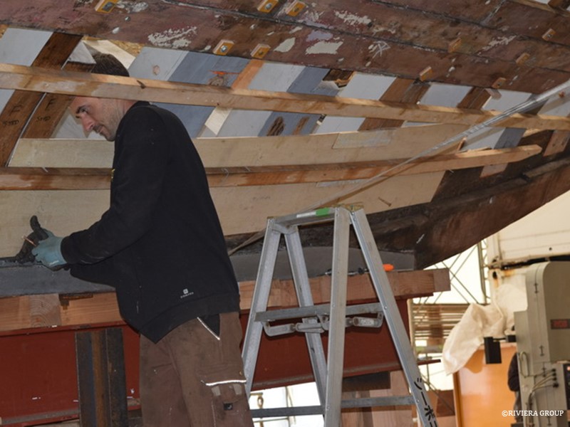
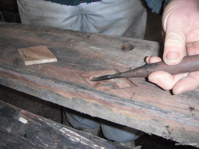
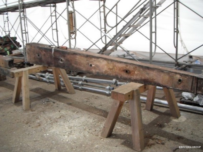
The lower edge of the keel timber had some damage from previous attempts to stop leaking with caulking. One or two areas needed to be cut out, and fresh timber was inserted.


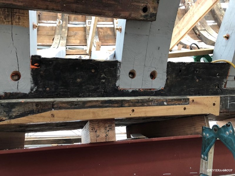
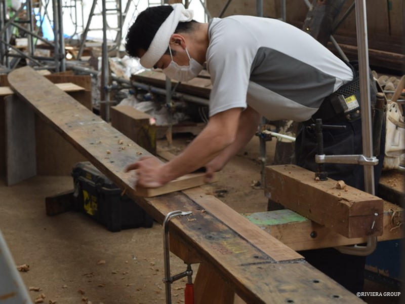
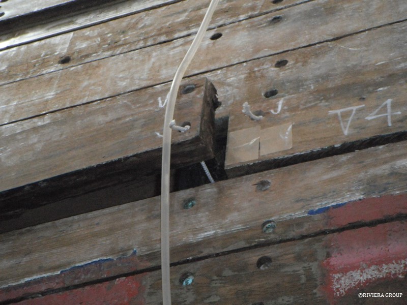
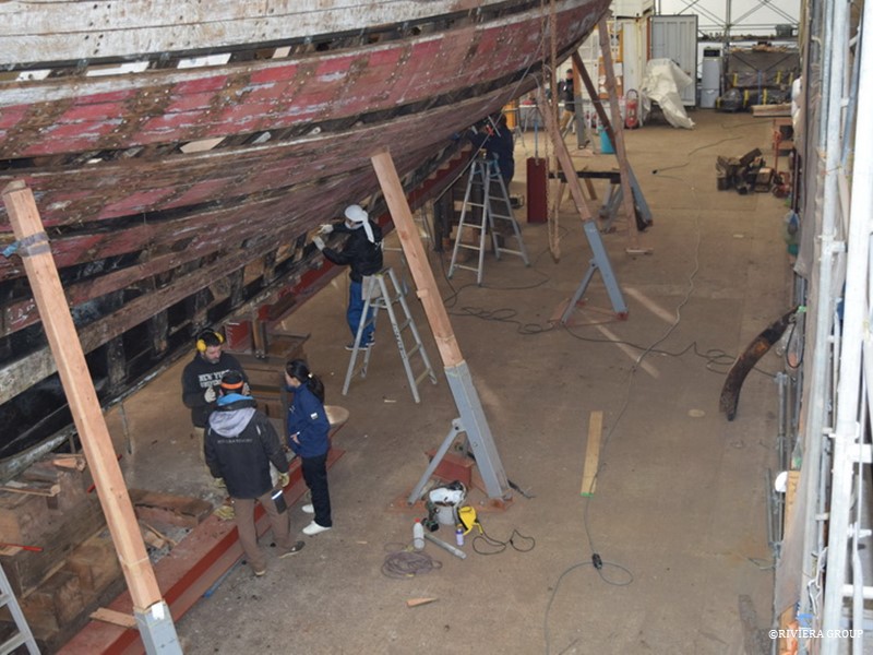
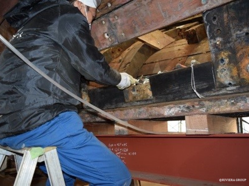
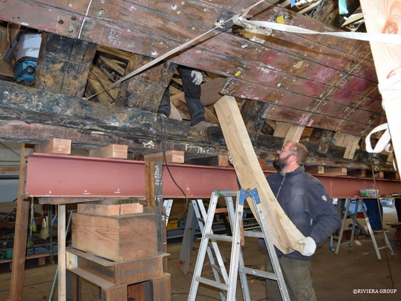
Repairing a damaged edge prior to refitting the garboard strake.

Follow Us

Restoration by RIVIERA GROUP

Restoration photos by Yoichi Yabe & RIVIERA GROUP

Text and photographs copyright © 2019
RIVIERA CO., LTD. All rights reserved.
Email : pr@riviera.co.jp

Blog — March 19-25, 2018

Blog — March 19-25, 2018

March 19-25,2018

One of the laminated frames, ready for its bevels.


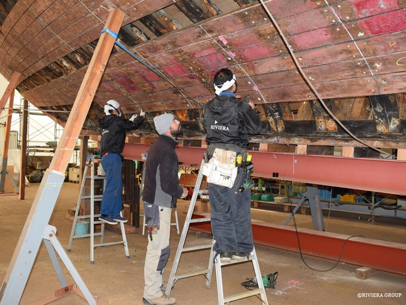
Pascal (above) grinds the head from a rivet. The bung hole is thoroughly cleared, and care is taken when the rivet is driven out not to damage the edge of the hole on the exterior of the plank. A spotter outside stops the work if it looks like the head of rivet might damage the hole. Our success rate of 99% wasn’t bad, since there are always one or two rivets that refuse to play by the rules.


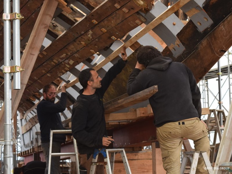
Kawashima is making a repair in the keel (above), while Richard checks a plywood pattern of the bronze plate against the boat (below).


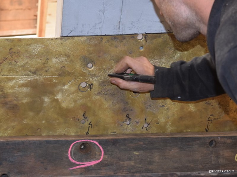
The copper alloy plate, probably naval brass, is a historical remnant of a repair done many years ago. We are refitting it to help reinforce the area around the mast base.


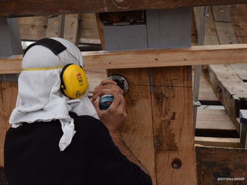
The plate presented some issues as we need to drive plank fastenings through the plate. Richard is marking the holes (above) so that the correct fastener can be used for each hole; some of them are for rivets and others for dumps.

Follow Us

Restoration by RIVIERA GROUP

Restoration photos by Yoichi Yabe & RIVIERA GROUP

Text and photographs copyright © 2019
RIVIERA CO., LTD. All rights reserved.
Email : pr@riviera.co.jp

Blog — March 12-18, 2018

Blog — March 12-18, 2018

March 12-18,2018

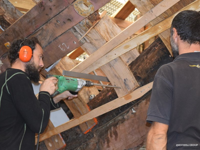
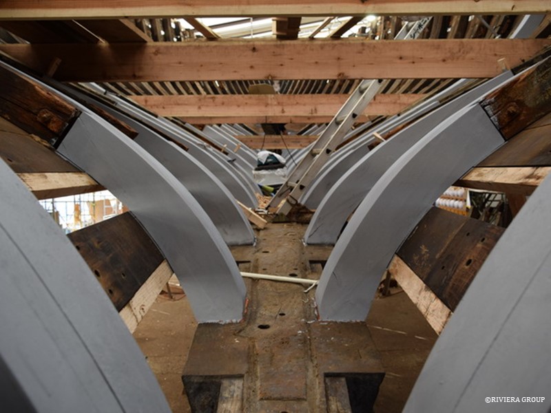
Nico drills for the naval brass drift that will be used at the base of each futtock as Richard guides the drill angle. Enough frame pairs are ready and faired to begin fastening them permanently into their sockets. The frames are bedded in red lead and linseed oil.


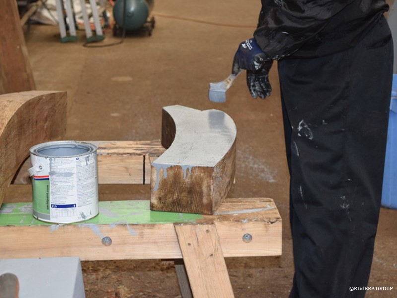
It was decided from the beginning to paint the interior of the hull. To help slow the drying and reduce shrinkage, a coat of good quality primer was applied. The primer is porous—so while not preventing timber from drying, it will show it down. As a bonus, the first coat of primer was in place before completion of the hull (below).


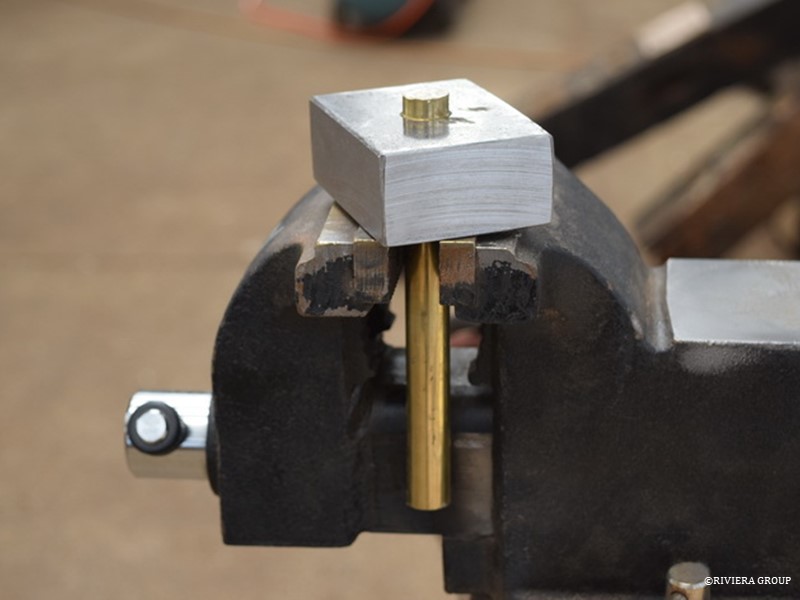
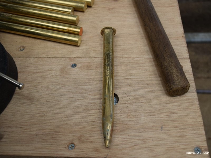
A rivet is fitted through a stout piece of steel (above) prior to creating a burr with a ballpein hammer. A production line has been started to complete the approximately 1500 rivets as well as the many drifts required to fasted the frame ends in their sockets. Each naval brass rivet and drift is handmade, and fitted with a very thick washer called a clench ring. Clenching is the process of turning a burr on the end of a rod with the clench ring, creating a head (below). Rivets hold the planking to the frames, while drifts are used to hold the frame ends to the keel timber.


Here are two drifts in place. The heads end up below the surface so they don’t interfere with the garboard plank when it is fitted over it.


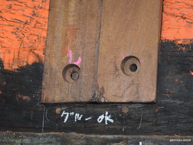
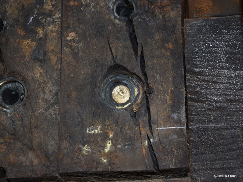
The shank of an original drift that broke at a spot just below the head while it was being removed. This will be pulled out with a slide hammer and some colorful language.


Kawashima has finished the repair on one of the planks, and is finishing it flush with the plank surface.


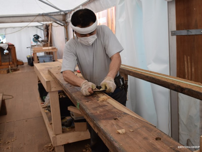
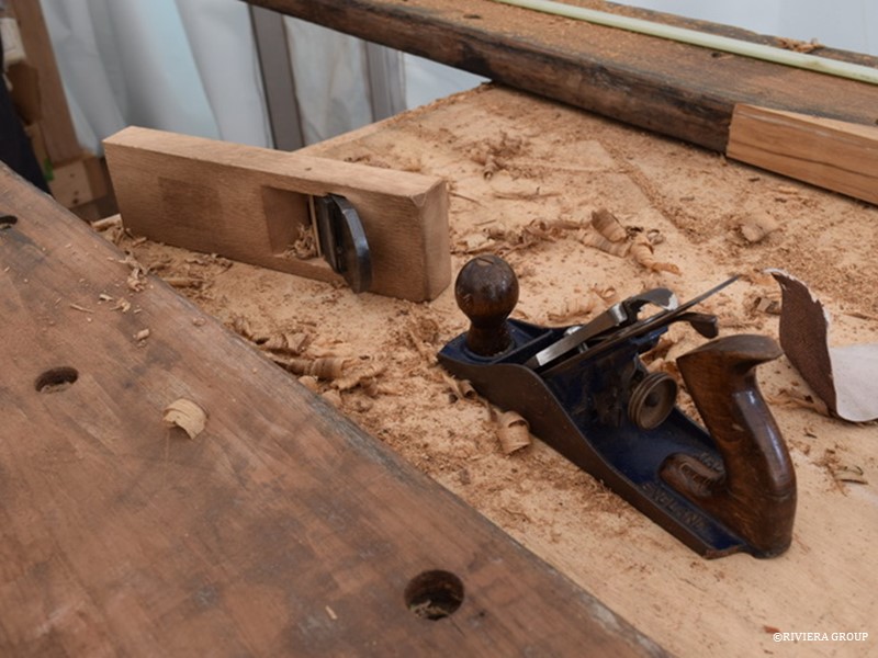
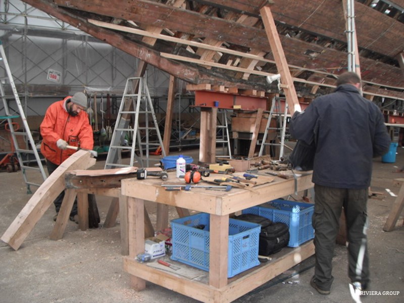
This Japanese plane (above) has been carefully laid on its side to protect its razor-sharp edge, while a western plane sits next to it, blade down. Shipwrights’ tools, especially in the early stages of restoration are prone to striking hidden nails, iron, and screws and a good edge is often quickly lost. This one has clearly lost its edge, and the owner is not concerned about leaving it blade down, a minor sin with a sharp plane.

Follow Us

Restoration by RIVIERA GROUP

Restoration photos by Yoichi Yabe & RIVIERA GROUP

Text and photographs copyright © 2019
RIVIERA CO., LTD. All rights reserved.
Email : pr@riviera.co.jp

Blog — February, 2018

Blog — February, 2018

February, 2018

Planks that have been damaged or have unwanted fastener holes are bunged, and a teak patch is glued over the top to restore the surface.
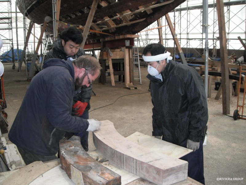
 

Lewis, Hashimoto, and Kawashima discuss the process of cutting out the futtocks.
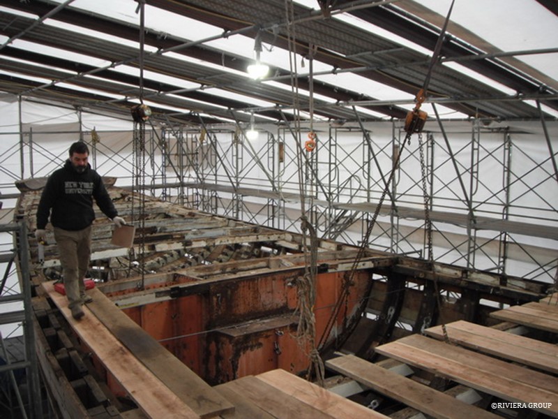
 

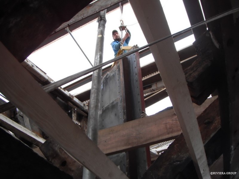
The riveted steel engine room bulkhead is removed with a chain hoist. We hoped that about 75 percent would be salvageable, but in the end decided to fabricate a replacement.
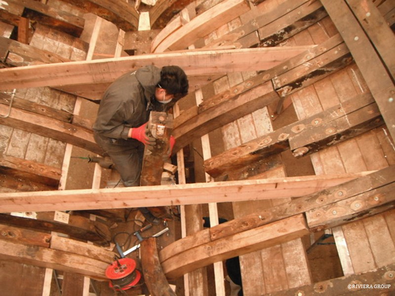
Work on replacing the futtocks is continuing, one by one.
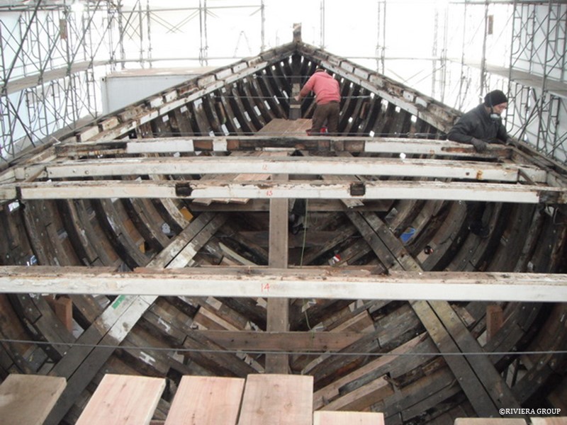
 

Taking the deck beams out turned out to be quicker than expected because of their poor condition. In fact, when the deck planks were released, some of them just fell out. They were in such bad condition that we didn’t have to make decisions on what was salvageable. Wires and bottle screws were fitted at stations to control the spreading of the hull at the edge of the deck.
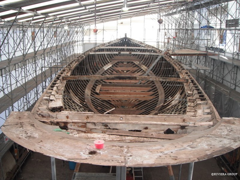
 

Only 3 or 4 beams are left at key positions to maintain the deck’s profile. There are no more obstructions and the entire hull is now accessible.
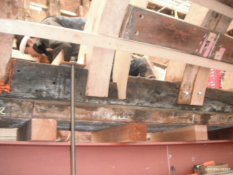
 

Work in the lower bilge marches on with new being added to old.
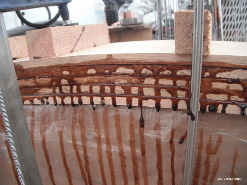
 

A number of laminating experiments were carried out to test the critical ambient temperature and timber moisture content.
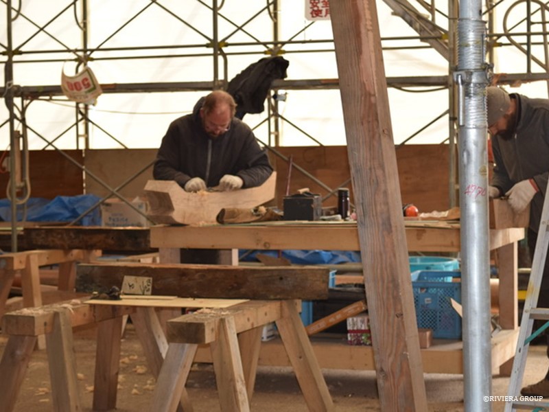
 

Lewis and Nico are making steady progress on the seemingly endless task of fitting the frames.
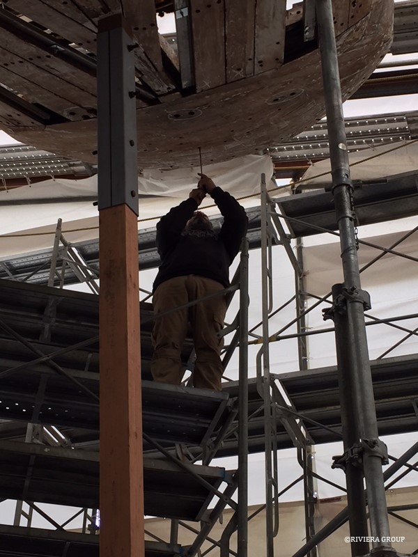
 

Paul surveys the stern chock before removal. We decided to replace the chock but we needed to collect data before removal. We also had to find all the fasteners so it could be removed smoothly. A number of repairs have been made over the years and we didn’t want to find any surprises. These chocks are usually only held in place by the hull planks and the deck, with perhaps a bolt through the end of the horn timber (the extension of the keel on top of the stern post that creates the backbone for the counter stern). Surprisingly, in Cynara’s case, it was held only by a single screw.
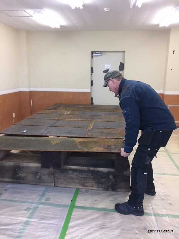
 

Jesper Olsen, a highly experienced Danish shipwright, joined the team. Experiments confirmed that it was too cold in the tent for laminating pieces, so his first job was to build a laminating table in one of the empty offices adjacent to the build tent. In the office, the air temperature and humidity could be kept constant, and the lighting was better. Here Jesper is laying steel sheets (the same ones used when we moved the keel) on top of sturdy pine blocks and levelled. Then a series of holes were drilled to provide anchor points for the brackets and bolts that allow different curvature patterns.
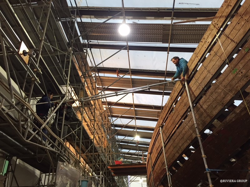
 

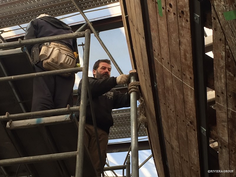
Scaffold shores are being extended from the hull to the scaffold of the tent for further stabilization.
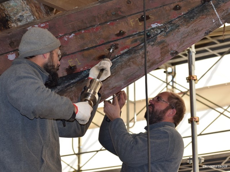
 

Nico is using a slide hammer to release the end of a plank at the stem.
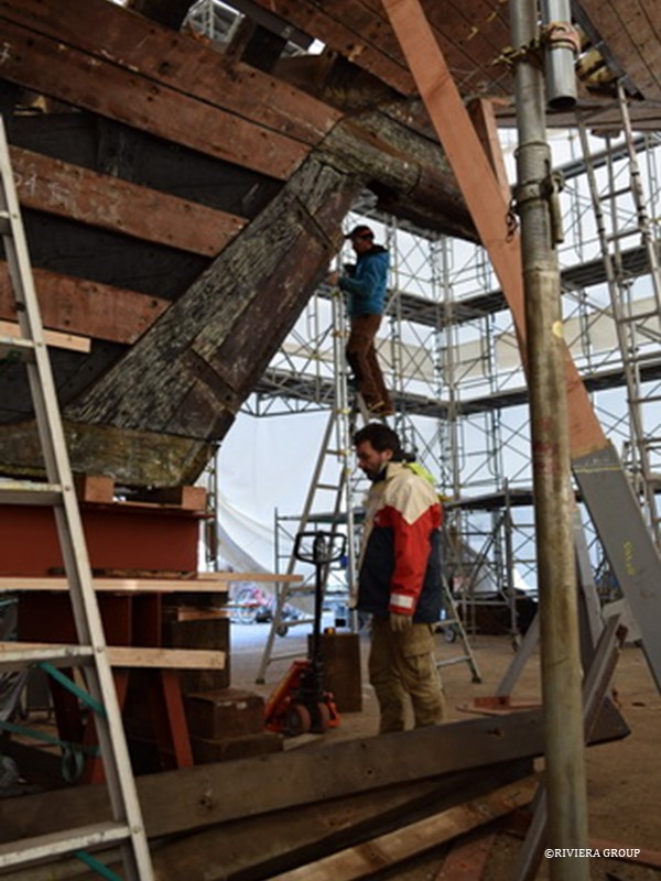
 

The strong back has been extended to run the entire length of the keel, and the steel table that Paul built has been fitted underneath. Ben balances on a ladder (above) as he works on the rudder cove, the hollow at the back of the stern post that takes the leading edge of the rudder.
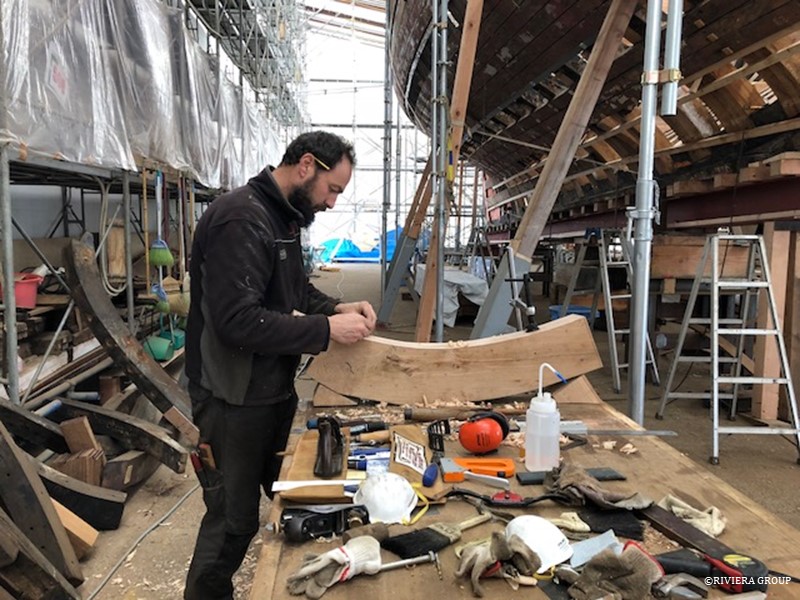
 

Some of the futtocks were very short. Some at the stern had a lot of curve, and we decided to make a few of them from laminated iroko. It was faster and cheaper to buy a small quantity of iroko, that we knew was dry, rather than mill large pieces of our oak stock into laminates.
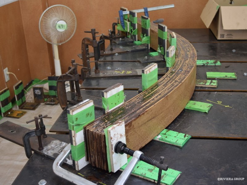
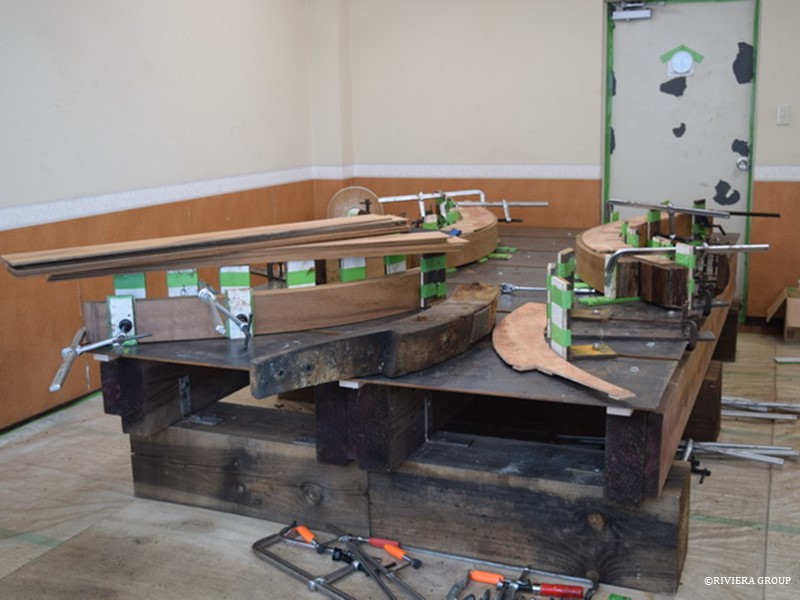


Jesper’s laminating table was quickly put to use, and it worked perfectly.
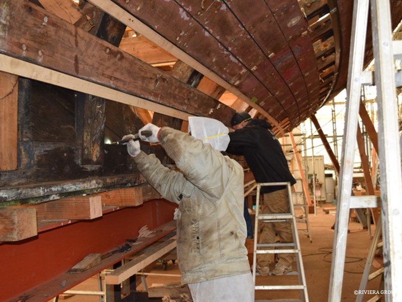
 

Meanwhile, work at the stern continues. Lead paint was applied to slow the drying of the stern knee. It was submerged for decades, so if it dries too quickly it could crack. Red lead was used because normal paint would have trouble drying on the damp surface.
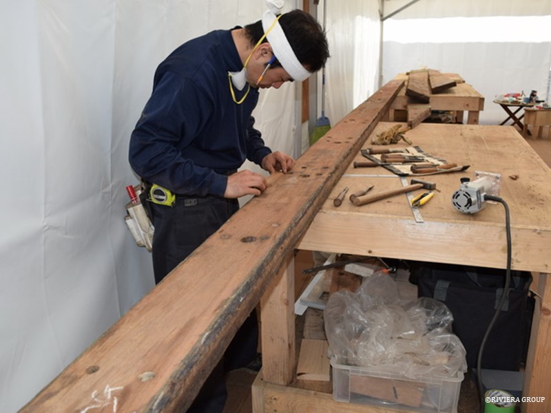
 

Kawashima examines one of the teak planks and makes small repairs. This was the first use of the new joinery tent, and it will never look this clean and dust free again.
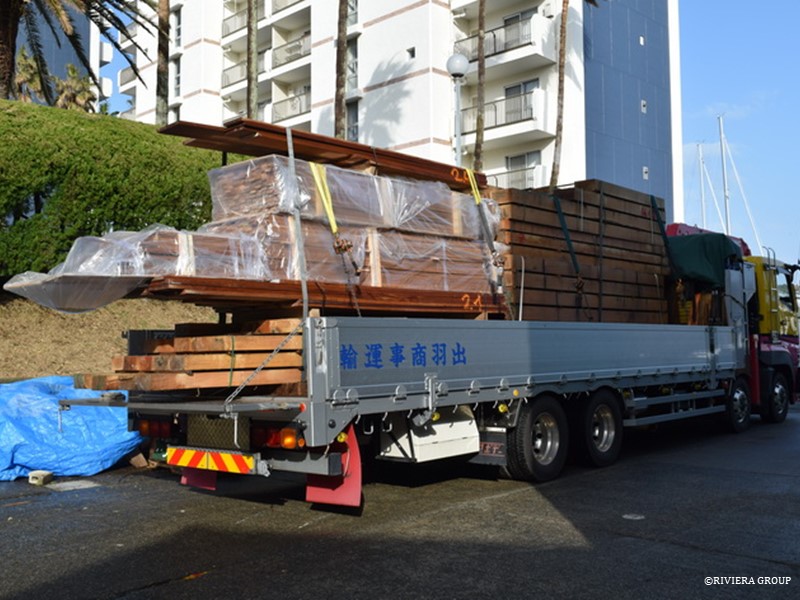
 

A shipment of timber—English oak and teak decking—arrives.
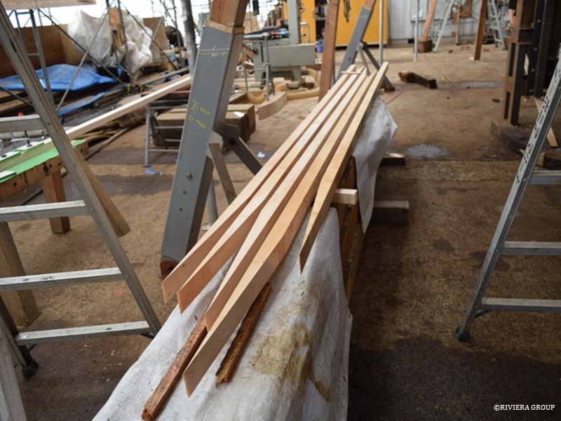
 

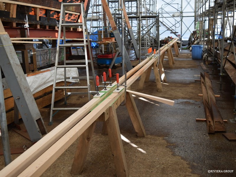
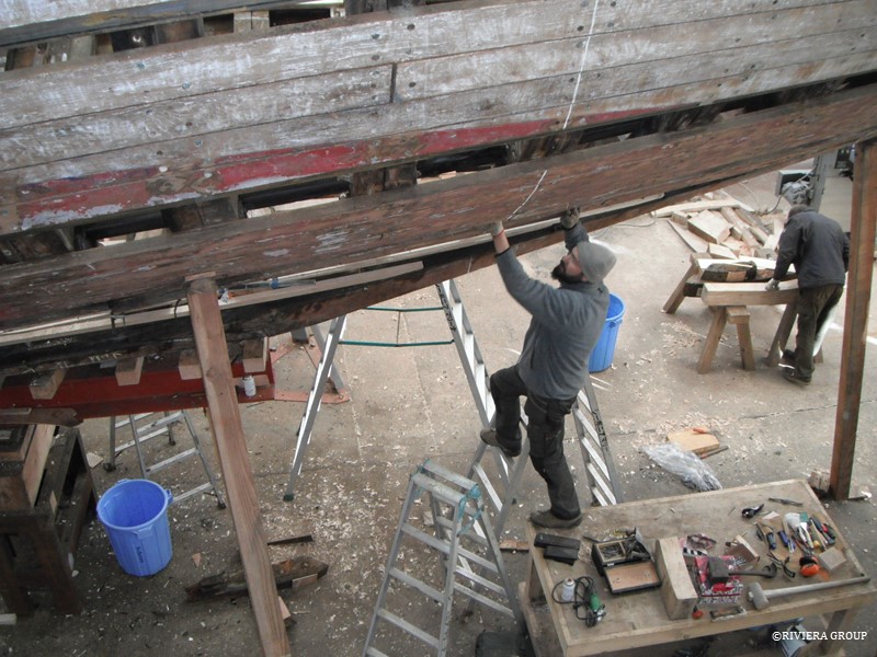
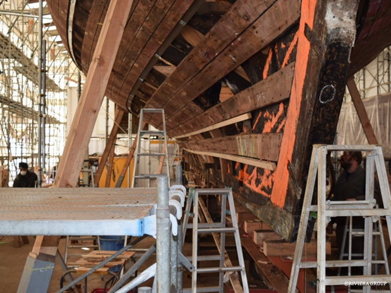
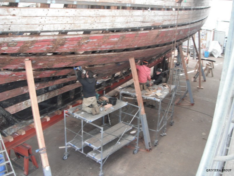
Clear grained hemlock supplied by the local timber merchant (top) was scarphed together to create long, continuous ribbands (above) that were fastened to the frames around the hull. These were used to check fairness and to have a reference to check against our line drawing. The old planking kept the original frames in position (below), but they weren’t good reference points as they were not necessarily fair or in the right position.

Follow Us

Restoration by RIVIERA GROUP

Restoration photos by Yoichi Yabe & RIVIERA GROUP

Text and photographs copyright © 2019
RIVIERA CO., LTD. All rights reserved.
Email : pr@riviera.co.jp

Blog — January, 2018

Blog — January, 2018

January, 2018


Carefully selected strakes, which are a run of planks from the stem to stern, are being removed by extracting the rivets and the ship nails (called dumps) with slide hammers and drifts. Kawashima (above) is drilling a hole into the head of a dump. It is then tapped with a thread before inserting the threaded end of a slide hammer and drawing it out.

A piece of string is tied through one of the holes to prevent the plank from springing out and falling to the ground when the opposite end is released. The planks may be very old, but they still retain their spring. The vertical tube is used as a water level in these early stages to monitor movement in the hull as strakes are released.


Nico Calderoni and Kawashima discuss a stubborn fastener.


After removal, the planks are cleaned, labelled, and stacked.


Ben is cleaning out the holes around the heads of the keel bolts. These are the long bolts that extend through the false keel, keel, and stern knee, and are difficult to remove.


Paul and Ben having one of their discussions on the plans with Takamiya.


Cleaning one of the sockets that housed a futtock, one of the curved rib-like timbers that make up the frame of the boat, after its removal.


Lewis is working on shaping one of the futtocks (above), and handing it to Nico, inside the boat (below) for a first fit.


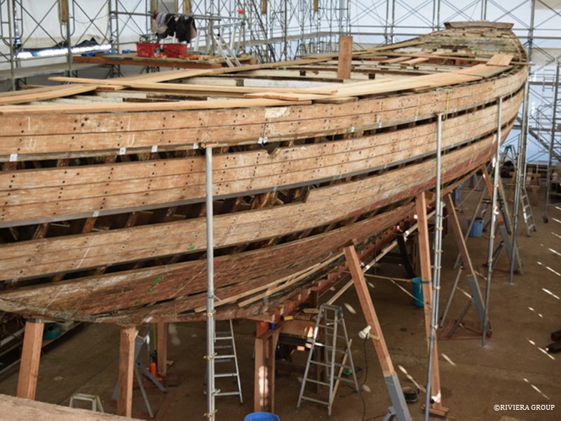
The careful selection of strakes to be removed allows the boat shape to be manipulated more easily. Some strakes are left in place to act as ribbands, keeping the frames in place while alternate pairs of lower futtocks are removed.


The lower section of the false keel was finally separated from the boat.


Chuck Demangeat, Cynara’s rigger, is onsite to check the deck layout. He’s discussing the positions for new fittings with Paul (above). The positions will more or less match the old ones, but this has to be checked at an early stage so that deck fittings don’t collide with existing hull fastenings and the strong points can be built to take the anticipated stresses and loads of the rig on the hull. It was interesting to see the methods that the original builders used, something that can only be seen when the hull is stripped. After more than 90 years of use, it was also necessary to examine the condition of these areas.


Wooden ribbands are fitted low down in the hull to make sure that the new futtocks being installed are fair.


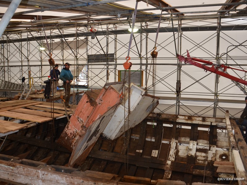
A chain block is used to remove a riveted steel bulkhead in the bow.


Nico is working on the lower stem section of the hull. There was no scaffolding at the time, so working with the heavy oak timbers off of ladders and benches was not easy.


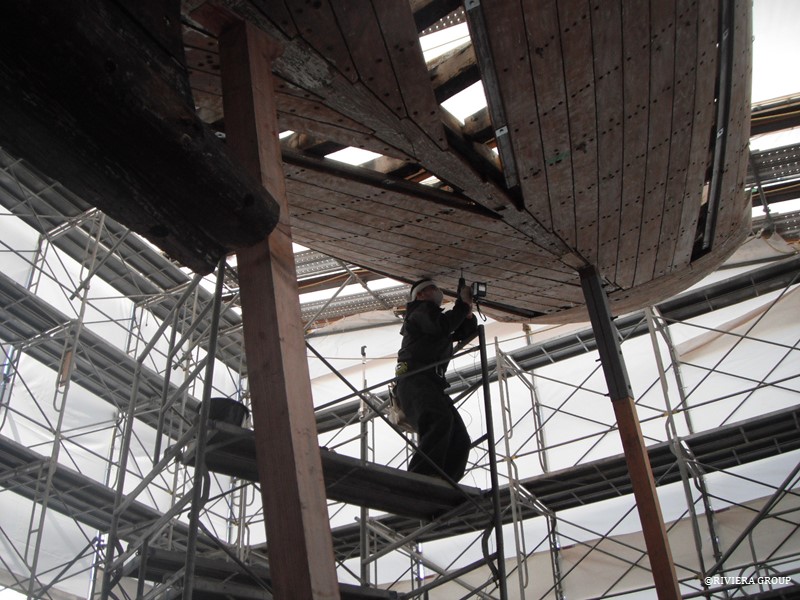
Paul is fitting adjustable scaffold “legs” at select stations around the hull. These allow the sheer line to be maintained and tweaked where necessary. The legs are securely bolted to a heavy steel box section ribband that was stretched around the hull two plank levels below the sheer line. They also help keep the hull vertical during the boat’s deconstruction and through the frequent earth tremors that Japan experiences.


Nico and Lewis working on the futtocks under the hull.


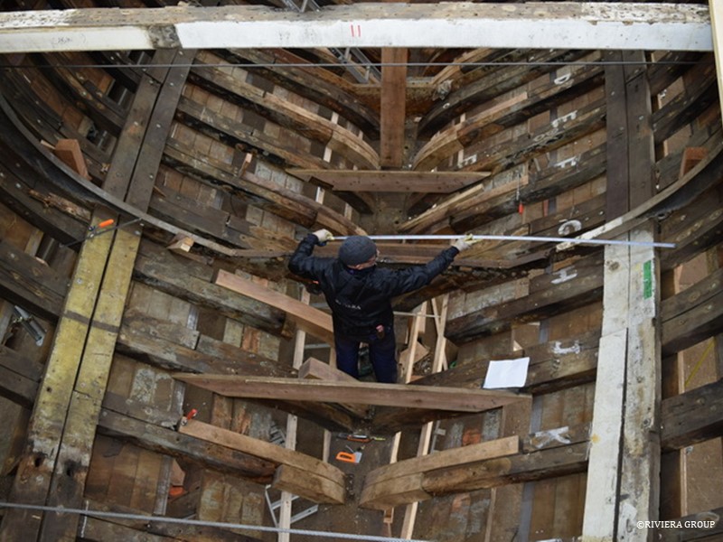
Pascal is in the bilges, cutting thwarts and braces to make sure the hull in the bilge area keeps it shape.


Cynara is slowly getting her original shape back, based on the original drawings. The hull already looks fairer, but there’s more to do before she matches the drawings.


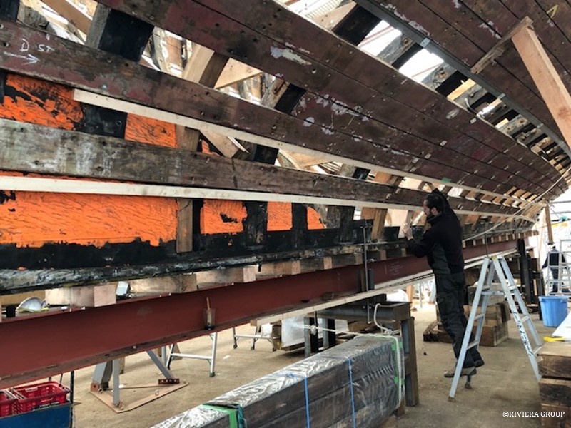
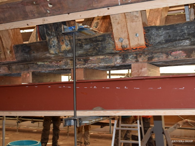
Clamps are used to secure the keel to the strong back I-beam. This is to take out any memory of the hog from the keel timber and ensure it stays flat and straight while work on Cynara continues. It also keeps the hull from moving during the random earthquakes.

Follow Us

Restoration by RIVIERA GROUP

Restoration photos by Yoichi Yabe & RIVIERA GROUP

Text and photographs copyright © 2019
RIVIERA CO., LTD. All rights reserved.
Email : pr@riviera.co.jp