Blog — December , 2017

Blog — December , 2017

December,  2017

This month saw the removal, packing and shipping of a number of items to be repaired, restored, or used as models for making new versions, when that was necessary.


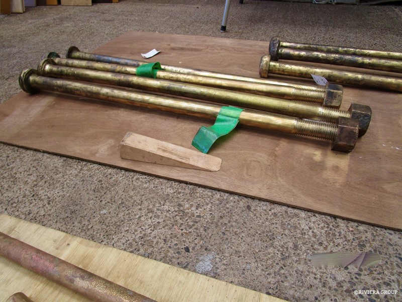
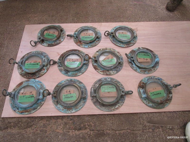
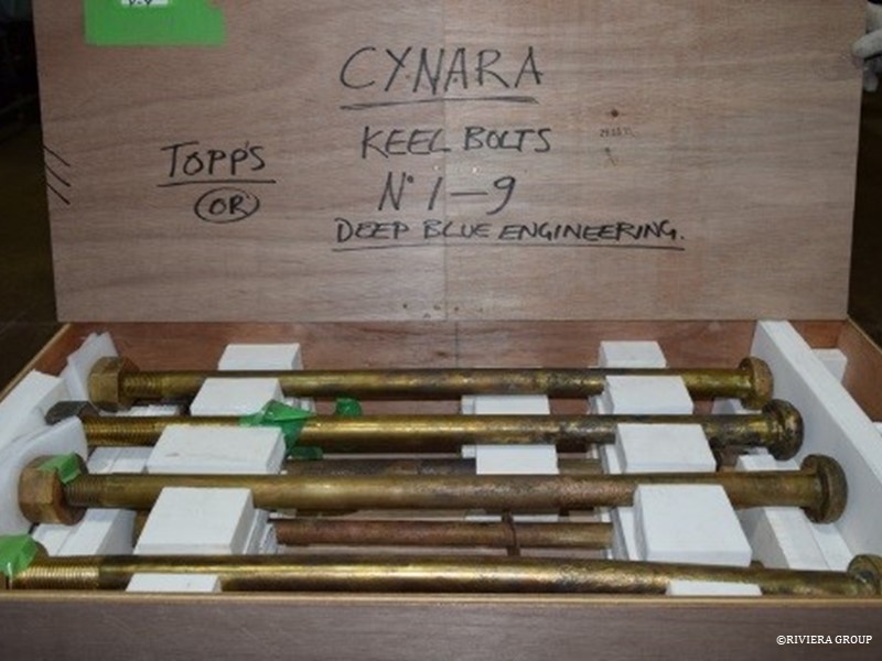
The bronze quadrant, which is part of the steering mechanism (above), the portholes and the keel bolts (below) were readied to be sent to the UK. A minor crack that had been repaired earlier was discovered in the quadrant, so we decided to send it along and have it checked over.
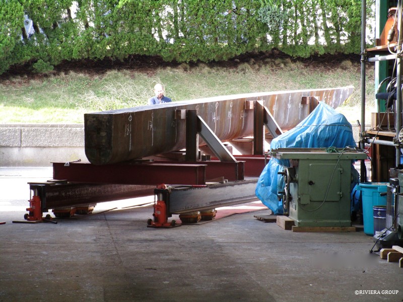
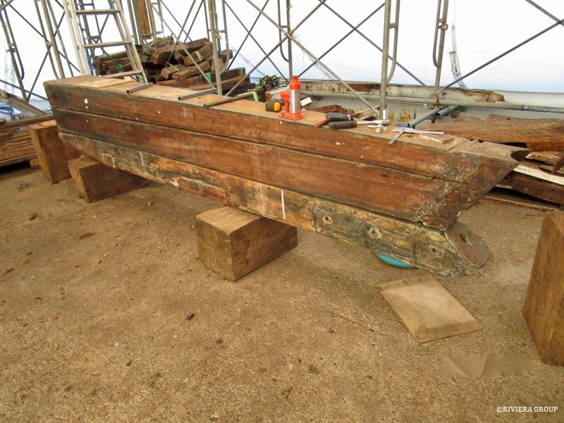
The false keel prior to removal (above) and after (below).
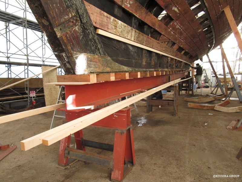
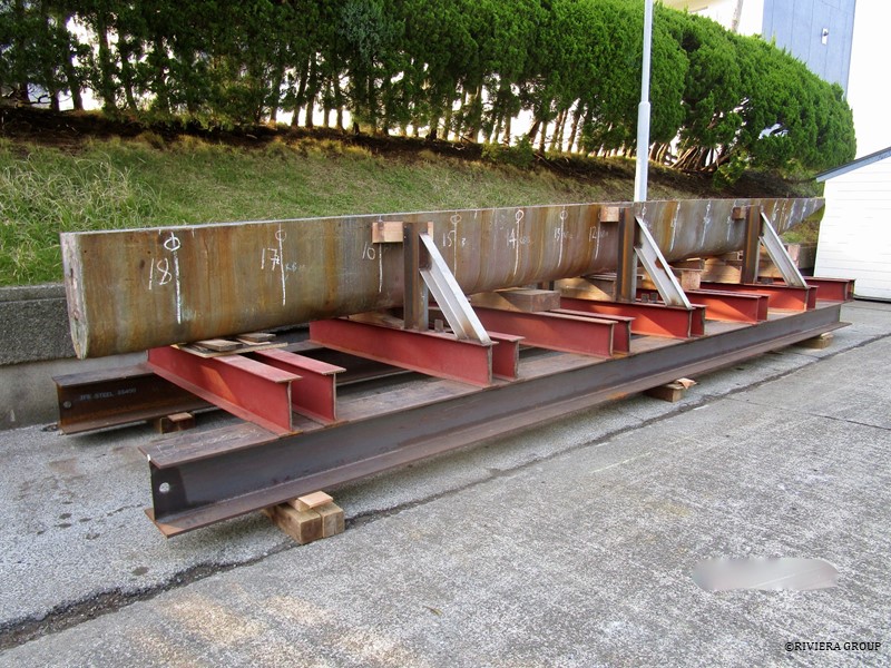
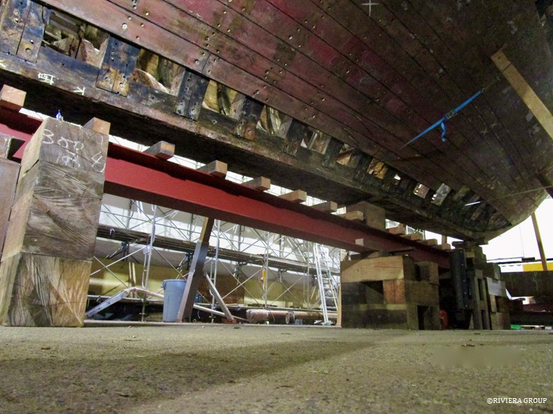
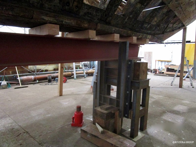
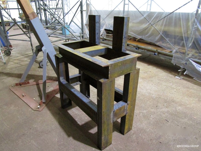
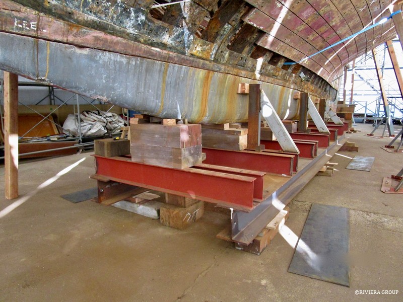
The large H beam that would be used as the strong back arrived, and was moved under the wood keel to support the yacht and keep the keel straight while work proceeds. To support the beam and the boat, heavy duty steel tables were welded onsite and securely bolted to the floor.
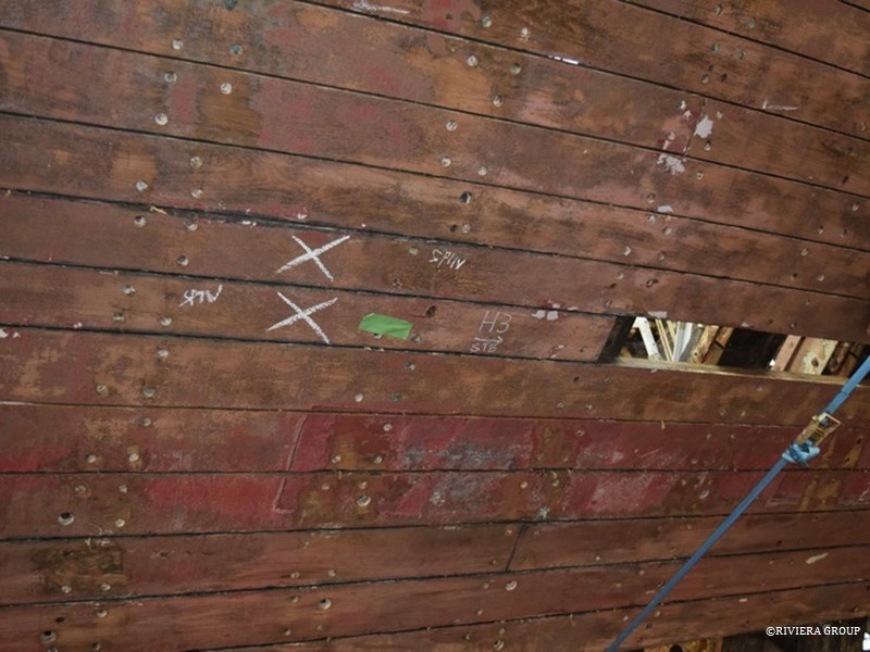
 

Certain strakes—a line of planks from stem to stern—were selected for removal (above). We tried to remove strakes that approximately followed the diagonal lines of the drawings. The process went like this: The bungs are removed from over the riven heads on the outside of each plank. Then the heads of the rivets are ground down to remove the burr over the clench rings that hold them.
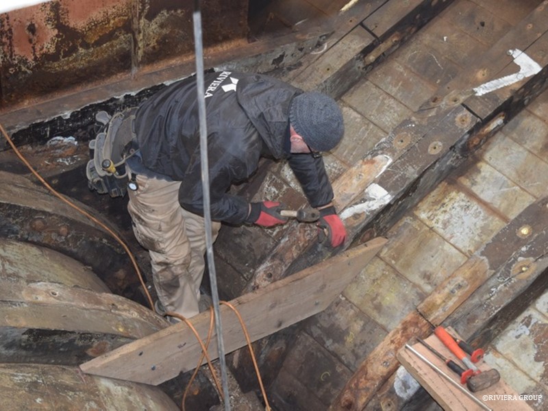
 

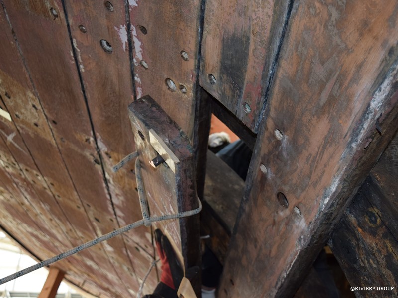
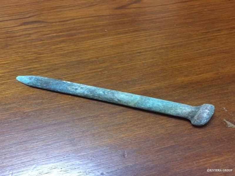
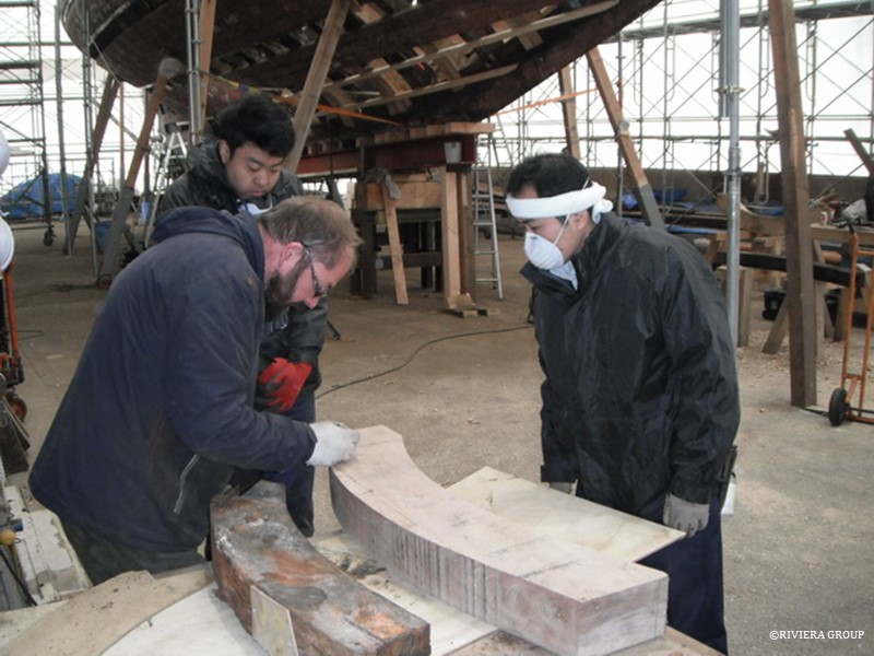
Then someone (Pascal in this case, above) drives the rivet out from the inside, while someone on the outside (Kawashima in this case, below) ensures the rivet comes out clean. Each plank on average had a 7/16 inch rivet and two 4 inch nails, or dumps, at each double frame.
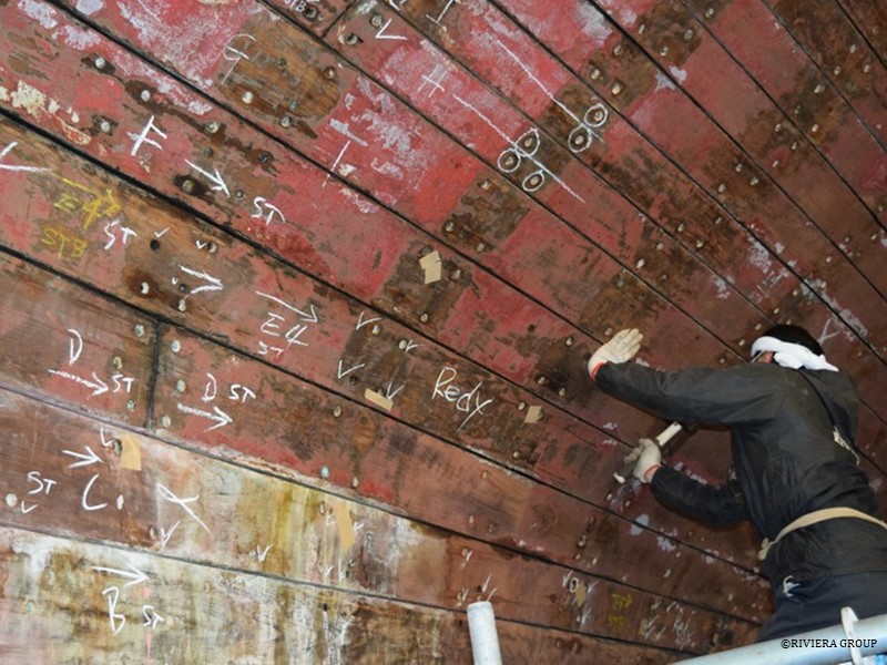
Planks are marked with a letter and a number and holes are highlighted depending on whether it’s a dump or a rivet to be removed. Even with the fastenings removed, remnants of oakum and swollen timber, submerged for decades, still makes them a challenge to release.
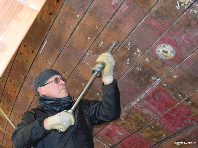
 

Pascal (above) removing one of the dumps (below).
 

The hull planks are always tough to remove, as they are swollen from 90 years of saturation. Making it even more difficult was the fact that the boat was out of shape, adding tension to the hull. Add to that the deep caulking and the “edge set” planks—meaning that straight planks are bent to fit the curve of the strake. After prising one end free (above), we lash it to something stout or add tension using a small block and tackle (below).
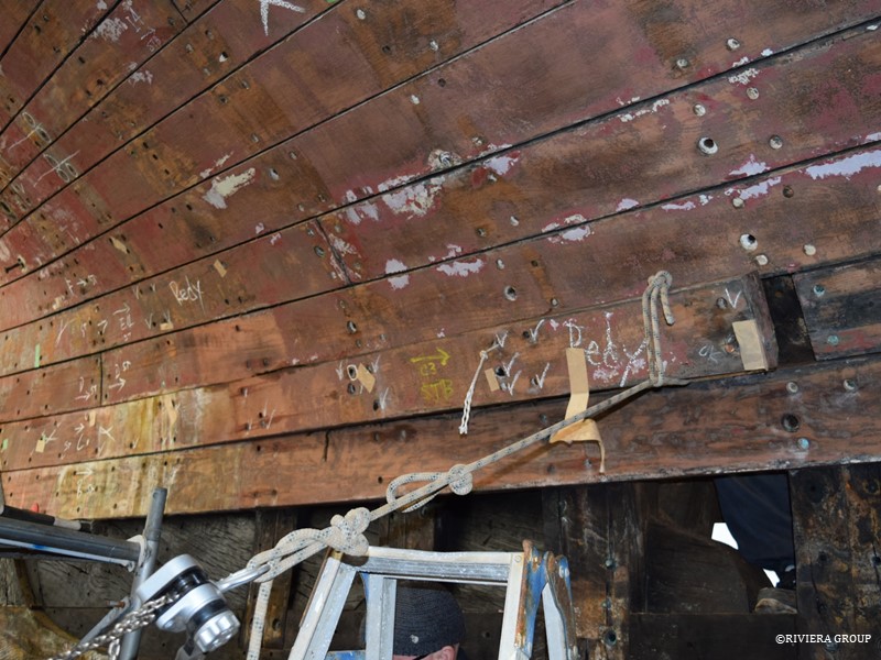
Holding the plank away from the hull as it is teased out helps to take the spring out of the 2-inch teak planks. It also allows room for a wedge between the plank and the frame. Each blow on the wege gains us a few millimeters as the stubborn planks come slowly out.
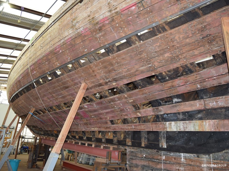
 

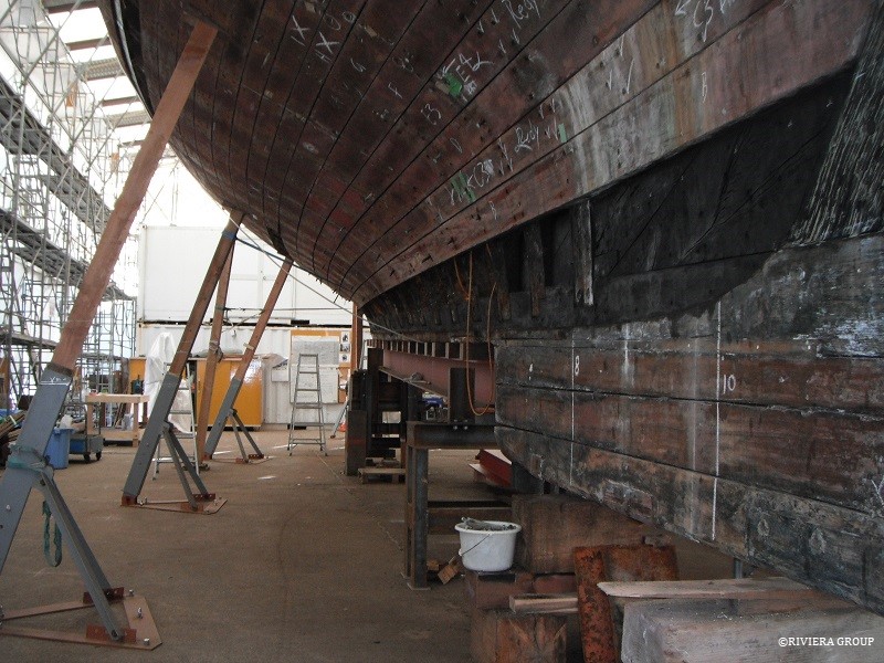
We remove full strakes to ease the tension in the hull, allowing it to move more easily. Broad strakes in the stern have been removed to expose the futtock ends at the stern knee.
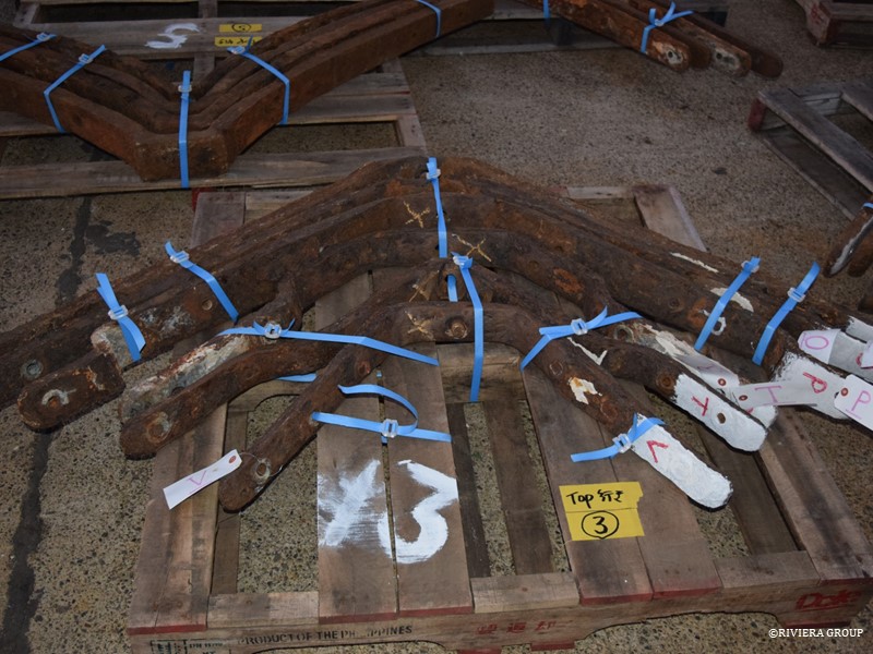
Wrought Iron floors are labelled and stacked on pallets to be shipped to the UK. It was decided it was going to be more efficient to send the original floors rather than fabricate complicated patterns against frames that were in poor condition and would be changed. The foundry could make accurate copies. Simple patterns were kept onsite so that new frames would maintain the correct profile but the complicated twist and shape of each floor could be forged using the originals. The floors are not cast, but forged from billets of iron. Each one is unique.
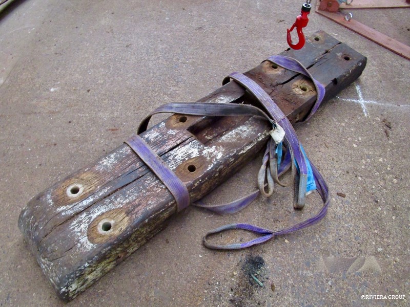
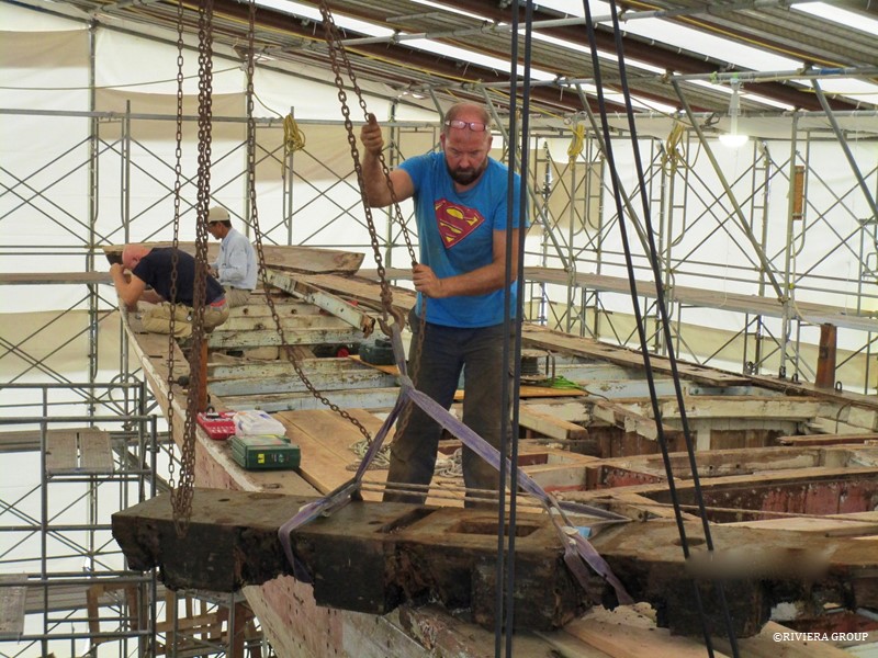
Also removed from the boat this month were the main mizzen step (above) and the generator bed (below).
Follow Us

Restoration by RIVIERA GROUP

Restoration photos by Yoichi Yabe & RIVIERA GROUP

Text and photographs copyright © 2019
RIVIERA CO., LTD. All rights reserved.
Email : pr@riviera.co.jp
Blog — November , 2017

Blog — November , 2017

November 2017

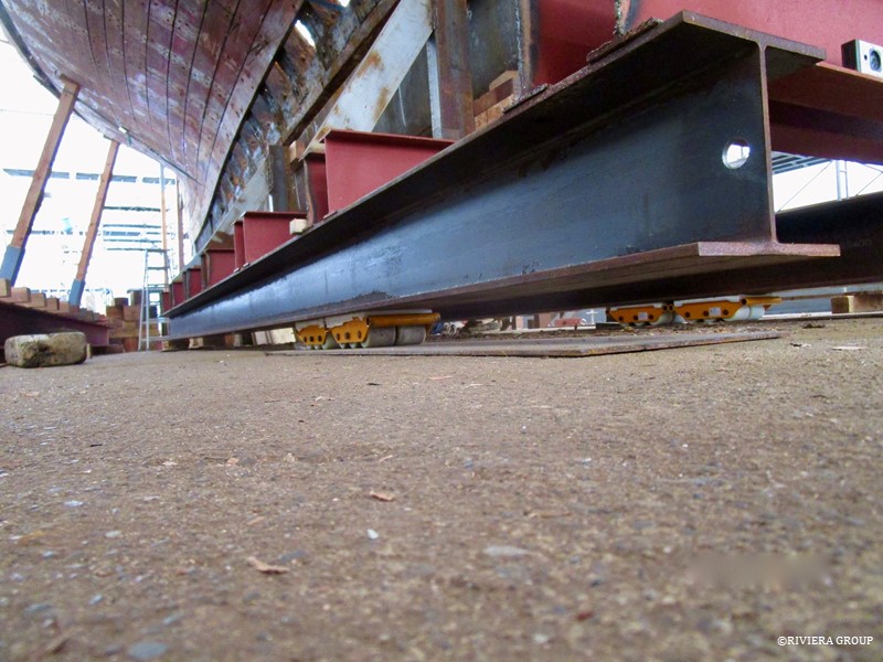
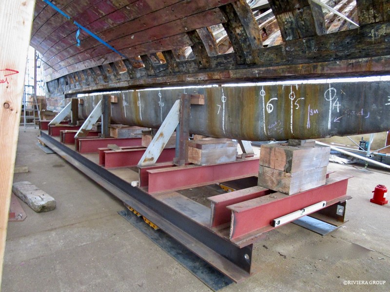
The plan to remove the ballast and straighten the boat moved ahead. It included the making of two heavy duty tables that would support the boat fore and aft. The tables (forward one above) were designed to support the strong back carrying the hull and allow height adjustments with the use of a 50-ton jack under each table. The ballast would then be lowered away from the hull.


The ballast was supported on cross beams welded to two long I-beams (above).


Skates were placed under the I-beams, so that the keel could be rolled out from under Cynara. The 8 skates, each with a 6-ton capacity, had to support the 25-ton weight of the ballast and the weight of the cradle.


The boat was stabilized and the steel frame jacked up to meet the ballast. (The chalk lines mark the locations where the keel bolts ran through the ballast.) Blocks were used to account for the angle and the irregular shape of the lead. As the cradle holding the ballast was lowered, a gap appeared above the ballast (above).


When the gap was large enough to allow it, the 25-ton ballast began its journey to a new location. It was moved inch-by-inch with pulled by steel cables and turfers anchored at strategic points in the concrete floor. For turns, the corners were jacked clear of the skates, and the skates were set in the new direction before the cradle was lowered back down on them. Steel sheets were placed over the floor to reduce any strain from stones or cracks in the concrete.


Lewis checking the angle of the skates as the ballast begins the final turn out of the machine shed. Though very slow, it was a remarkably smooth journey once everything was set. The hardest part was moving the awkward steel sheets.


The hog is clearly visible in this shot.


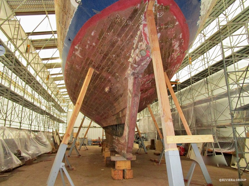
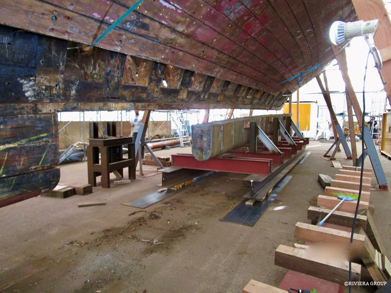
A strong back was created using four-inch blocks spaced evenly on an I-beam that ran between the two tables. This was then jacked up to the centerline to give the necessary support. The weight was taken by the beam and the tables, and the 4-inch blocks let us access any bolts in the underside of the keel. This was when she was at her most precarious, balanced on timber shores with nothing supporting the centerline. Now we could focus on straightening the distortion of many years in the keel timber, and jack it up to the correct angle.

Follow Us

Restoration by RIVIERA GROUP

Restoration photos by Yoichi Yabe & RIVIERA GROUP

Text and photographs copyright © 2019
RIVIERA CO., LTD. All rights reserved.
Email : pr@riviera.co.jp
Blog — October , 2017

Blog — October , 2017

October 2017

The keel bolts were removed, cleaned and measured. Of the 18 keel bolts, only three of the main ones and two smaller ones at the stem ended up being replaced, even though some were slightly bent. They were sent for inspection using a dye which shows any hairline cracks that might be invisible to the naked eye. The nuts were replaced.


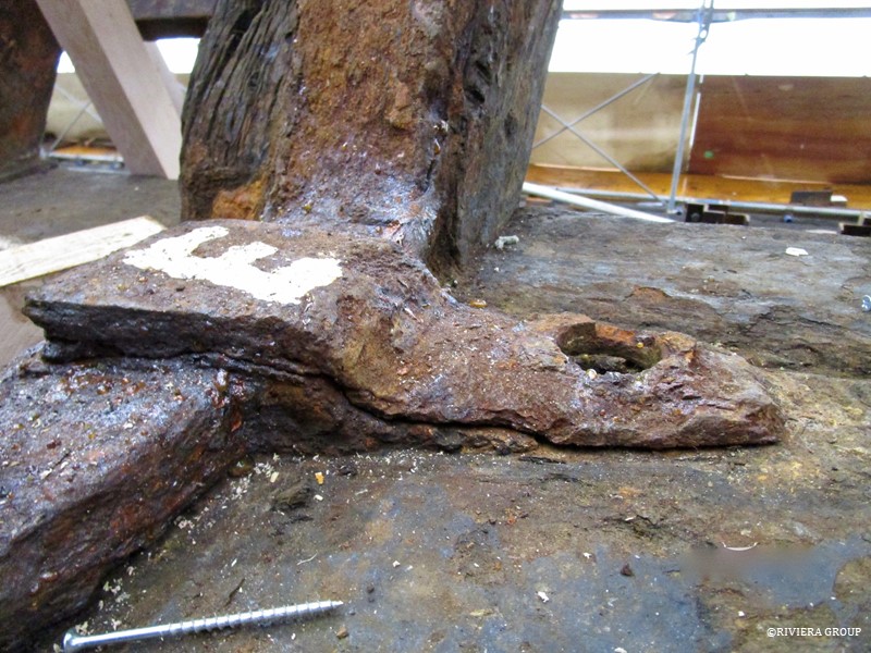
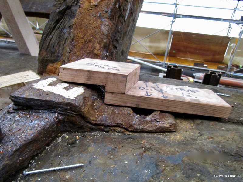
It was clear that the iron clips that connected the keel bolts to the iron floors were corroded beyond repair (above). We made wooden models (below) that were sent off to Topp & Co. in the UK so that new clips could be forged, along with the floors. The wooden patterns only recorded the principal dimensions. The sharp edges of the pattern were eliminated in the forging process.


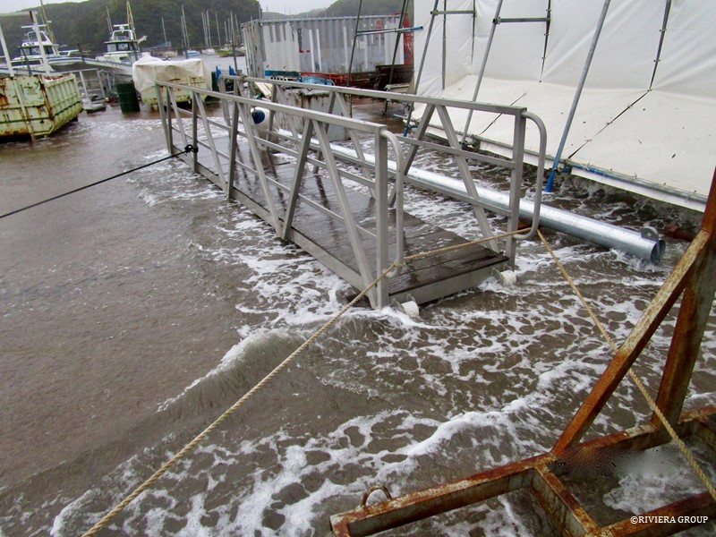
Late summer and autumn is typhoon season, and we were hit with a fairly large one on October 17. The storm surge swept over the marina and carried the main boom away. (It was later found underneath a beached boat across the bay.) In the above photo, the storm surge has reached the side of the shed, 100 meters away from the edge of the dock.


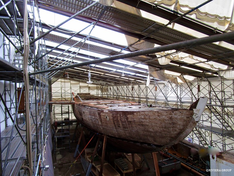
The high winds shredded the roof of the tent (above), and gave the boat a soaking. Otherwise, it was undamaged.

Follow Us

Restoration by RIVIERA GROUP

Restoration photos by Yoichi Yabe & RIVIERA GROUP

Text and photographs copyright © 2019
RIVIERA CO., LTD. All rights reserved.
Email : pr@riviera.co.jp
Blog — September , 2017

Blog — September , 2017

September 2017

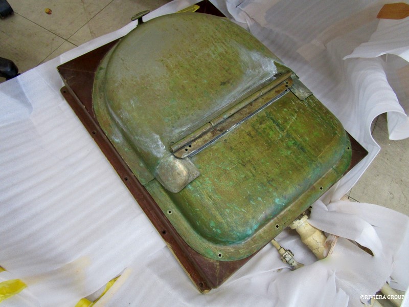
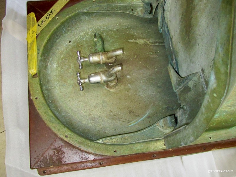
We continued cataloguing and storing items from the interior. The ingenuity of this folding sink (above and below) was fascinating. It is now displayed in the ship’s museum on the Seabornia Marina site.


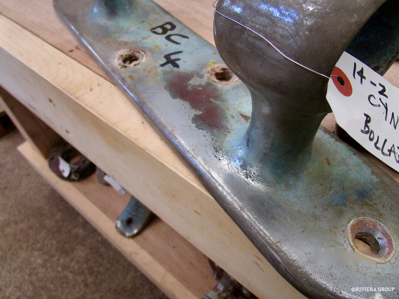
The remains of the beautiful nickel plating on the bronze cleats are still visible on these originals. These were set aside to be cleaned, restored, polished and reused.


Lewis took out the mast step for cleaning and restoration with a chain hoist. He also helped set up the joinery shed (below) next to the large shed that housed Cynara.


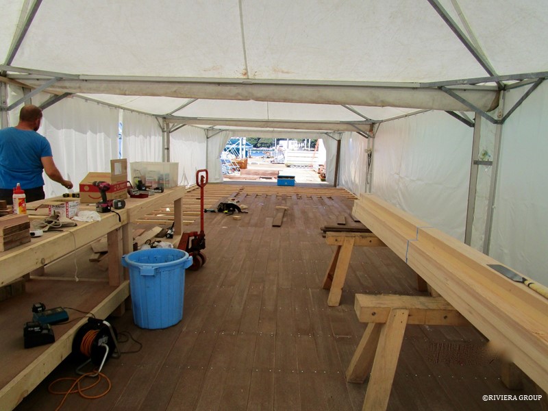
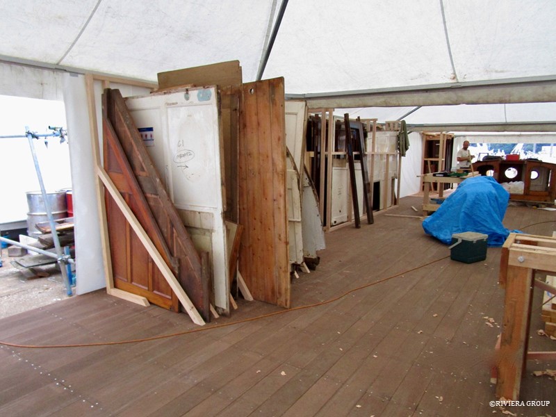
 In the joinery shed we stored interior parts (mainly the pine panels), some of which would be restored. The rack that is visible above was used mainly to house the white painted paneled bulkheads. (We were optimistic at the time that some could be stripped, repaired and reused. Because of changes in the layout, and the fact that many had suffered from water damage, in the end they were used for reference.)


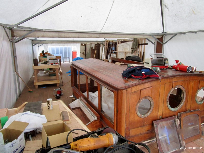
The deck house was also stored in the shed. Here, the peripherals—the glass, the sliding hatch, etc.—are being removed.

Follow Us

Restoration by RIVIERA GROUP

Restoration photos by Yoichi Yabe & RIVIERA GROUP

Text and photographs copyright © 2019
RIVIERA CO., LTD. All rights reserved.
Email : pr@riviera.co.jp
Blog — August , 2017

Blog — August , 2017

August  2017

In early summer, we began planning the removal of the keel in order to straighten the hog.


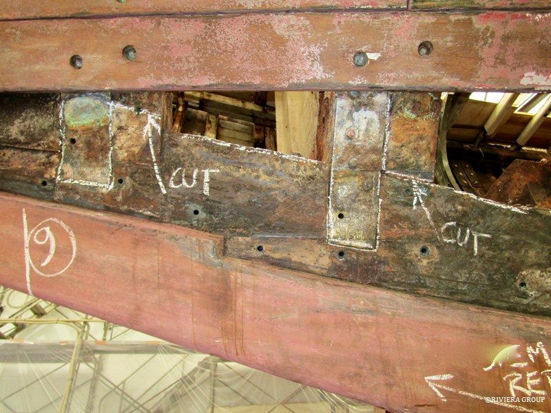
 As we began removing the planks, we found evidence of work that had been done earlier. At some point over the years, the lower half of the stem had been replaced. We could see where the bottom of the double frames had been cut through to allow the removal of this section. Bronze straps (outlined in chalk above) had been installed to bridge the joint between the lower frame end and the new section of stem. The repair had been done not with oak, but with iroko, an African hardwood with properties similar to teak. That suggests that it was done sometime during the 60’s, when the use of iroko was prevalent in Europe, but there are no records.
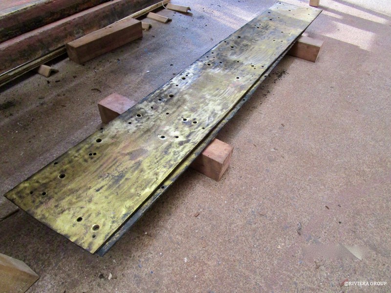
 

On either side of the main mast step a large naval brass plate (above) was fitted to add extra strength in this area. We decided to use these in the restoration as we thought it did no harm having the extra stiffness.


Follow Us

Restoration by RIVIERA GROUP

Restoration photos by Yoichi Yabe & RIVIERA GROUP

Text and photographs copyright © 2019
RIVIERA CO., LTD. All rights reserved.
Email : pr@riviera.co.jp