Blog — Monday , 6  May, 2019

Blog — Monday , 6 May, 2019

Wednesday, May 1, 2019

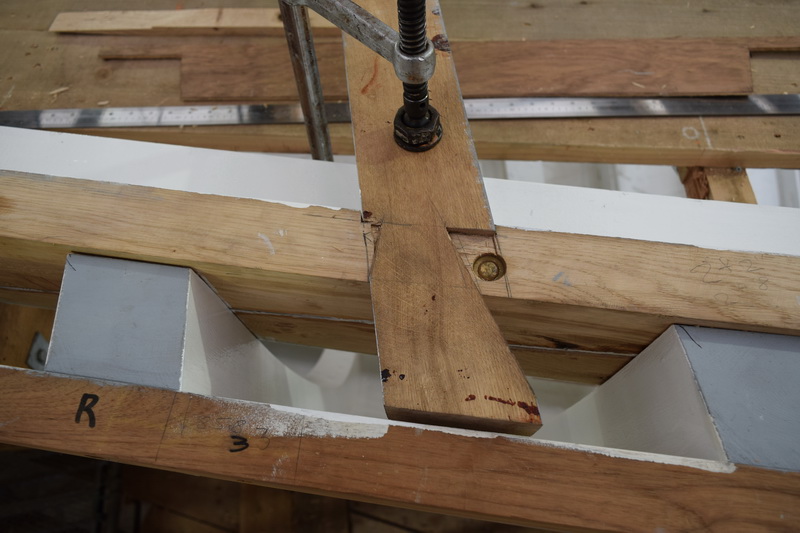
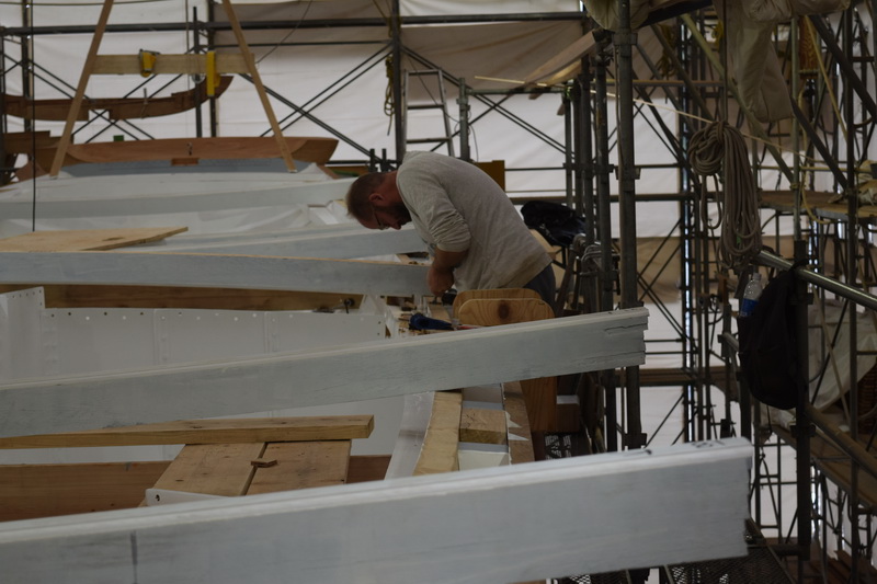
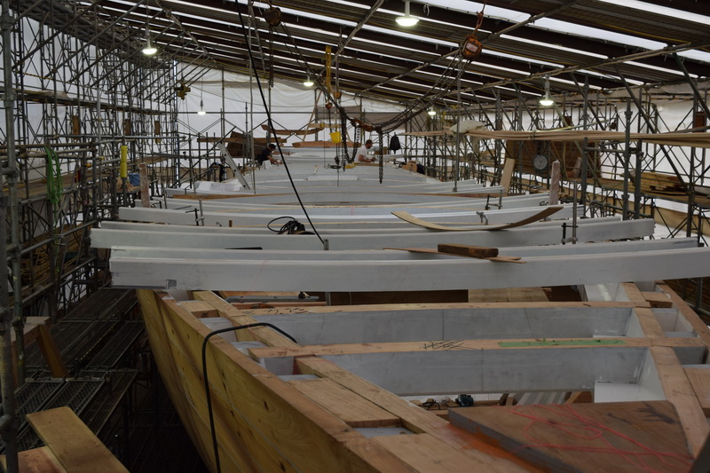
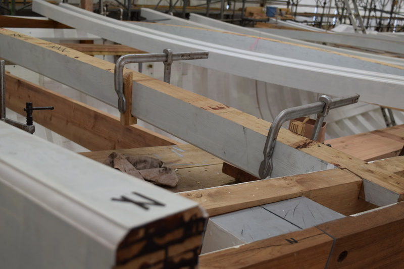
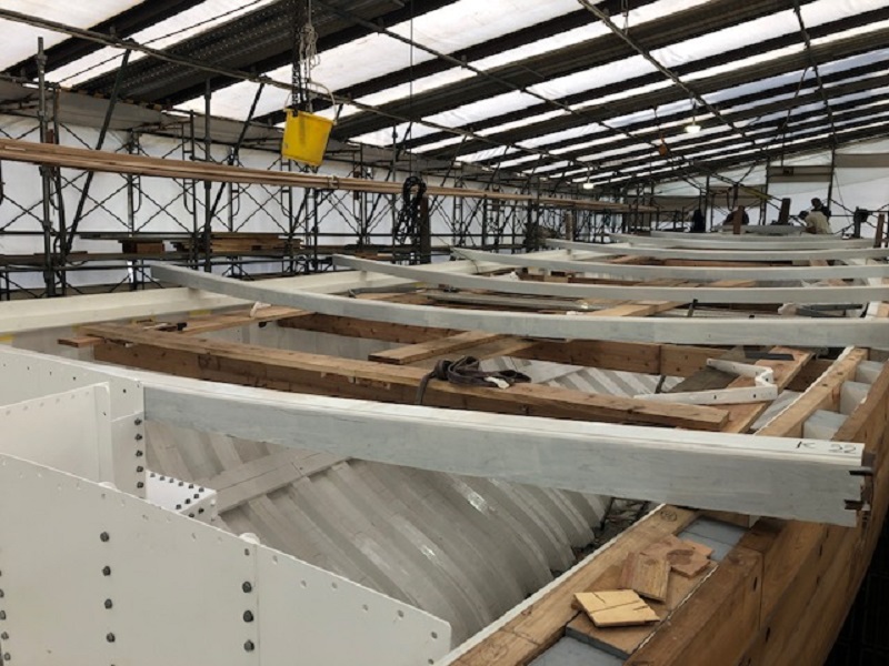
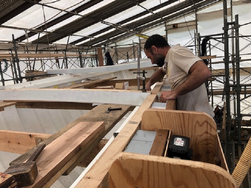
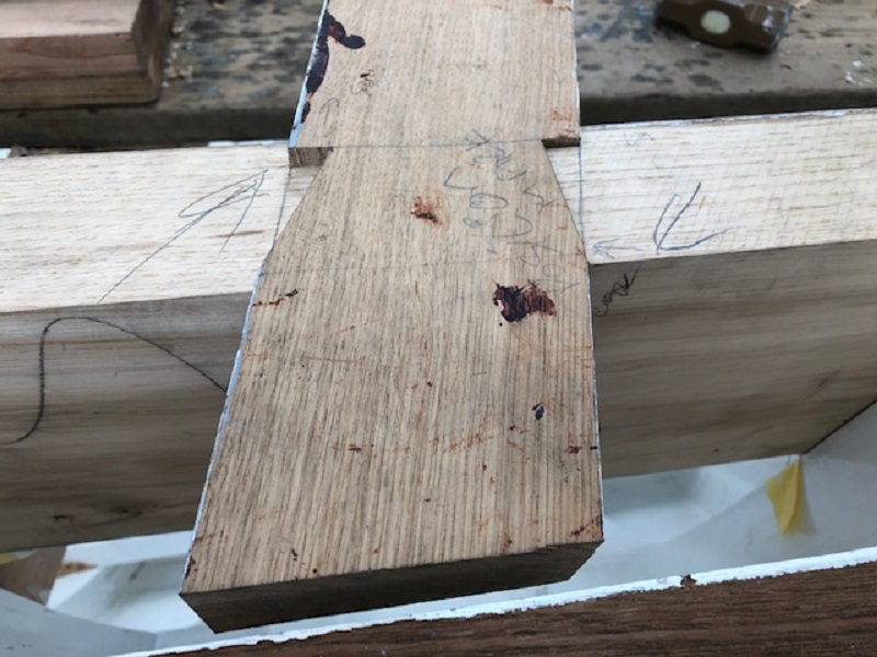
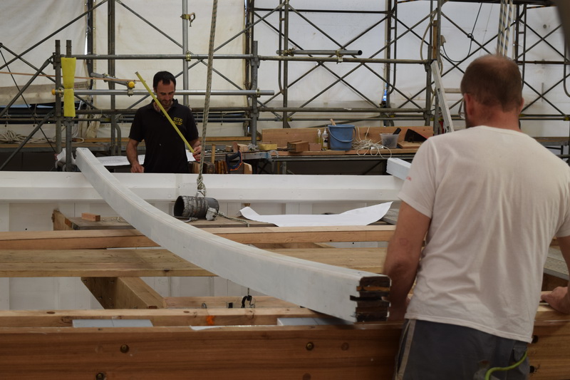
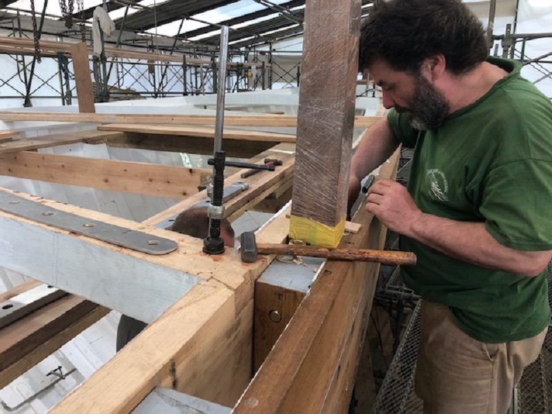
Lewis fitting one of the deck beams, dovetailing one of the ends into the beam shelf.


The wood stanchions are being set out in order, ready for their first fit.


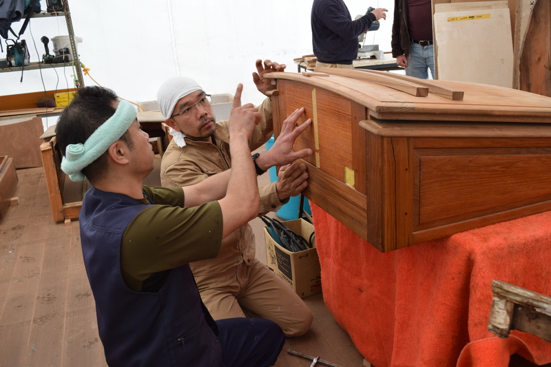
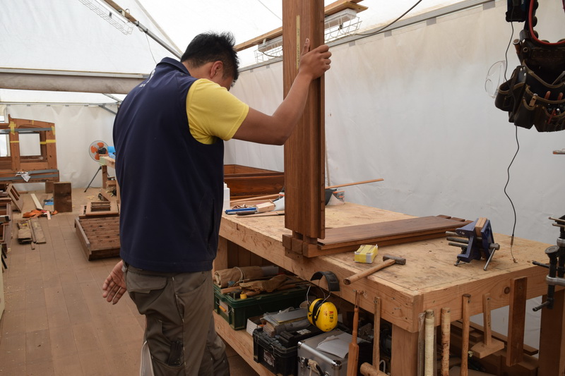
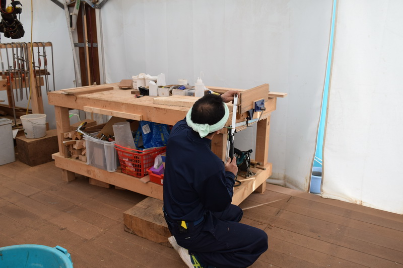
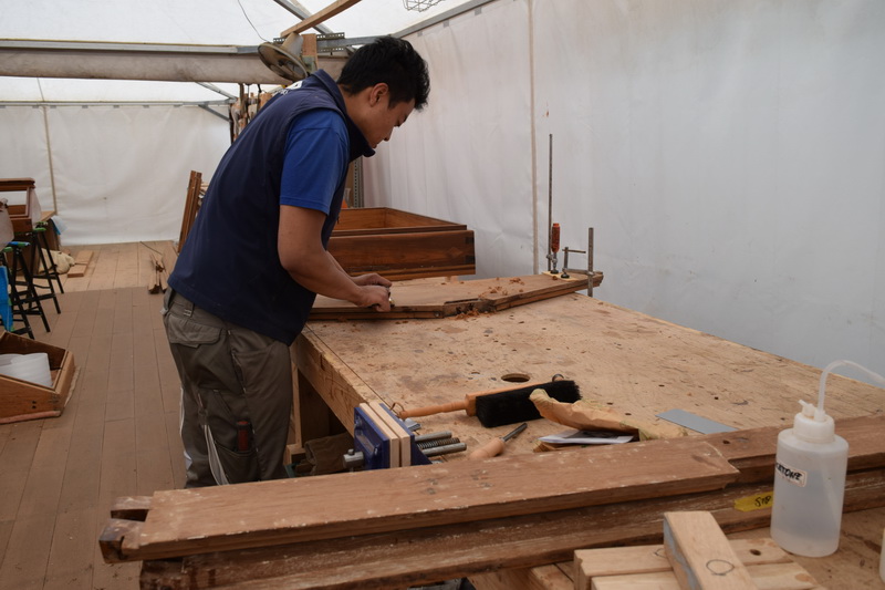
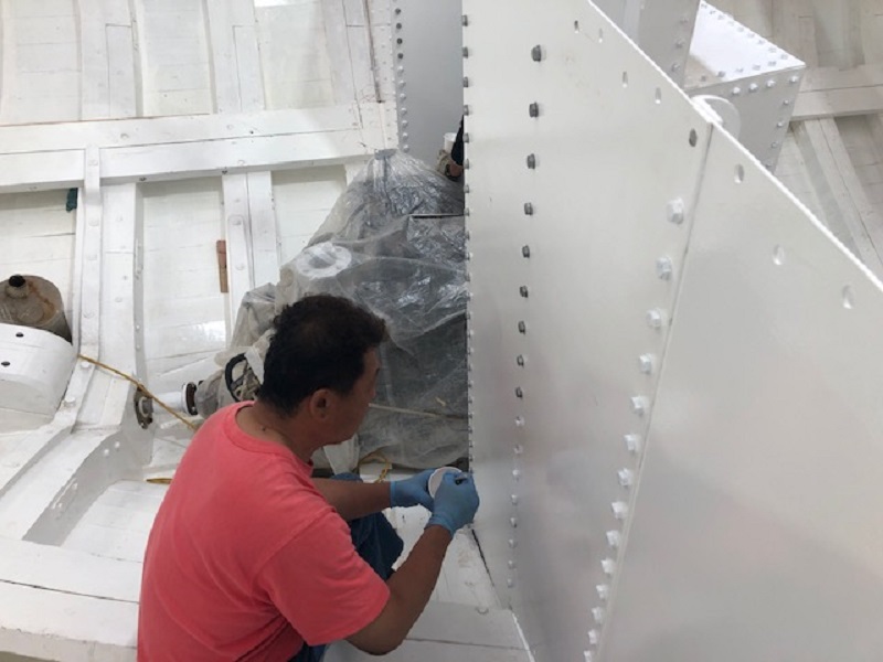
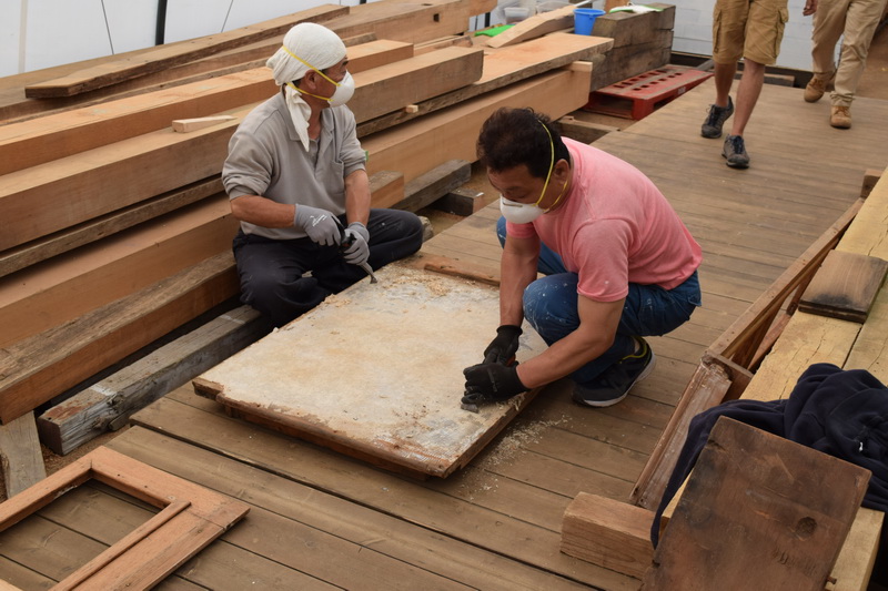
Inside the tent where the interior work is being done, Kawashima and Hashimoto are working on the restoration of the crew companionway hatch.


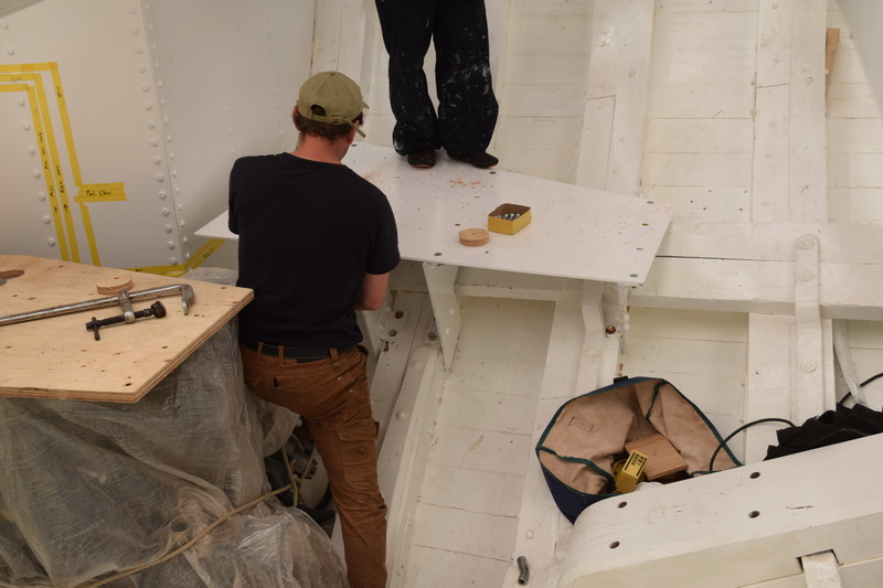
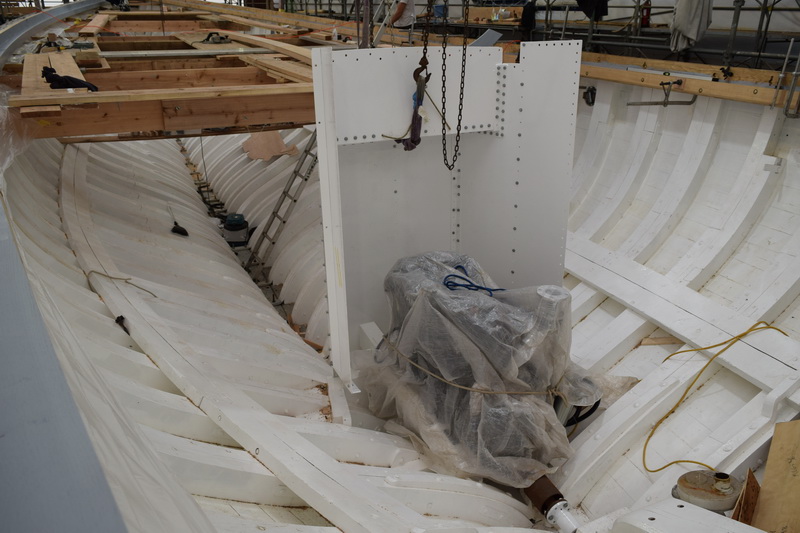
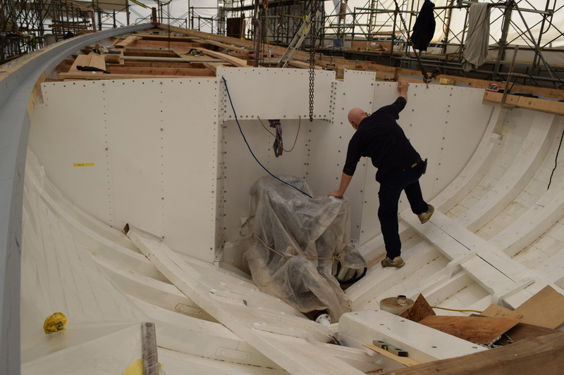
Now that the engine room bulkhead has been installed, Ben is able to work on fitting the generator bed.


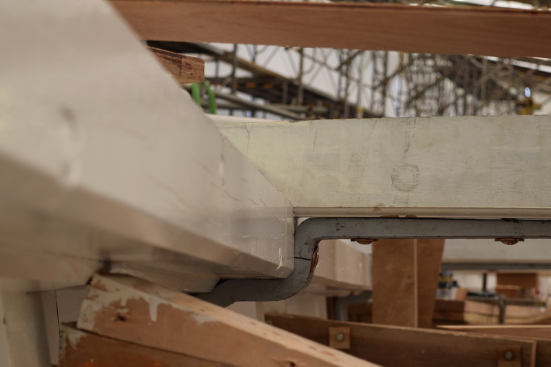
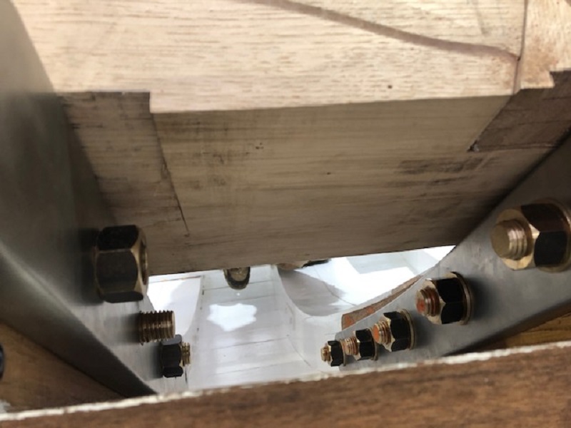
It’s hard to make out in this photo, but the grey piece under the beam is a wrought iron knee that’s been fitted to support the beam.


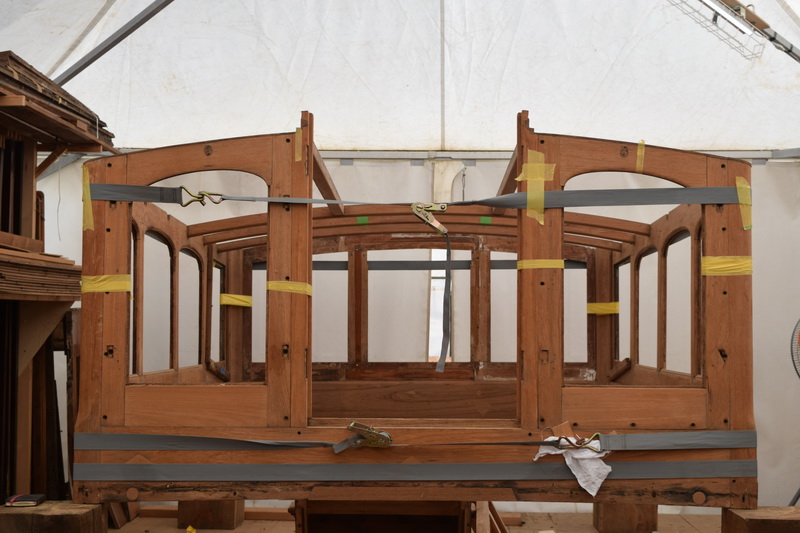
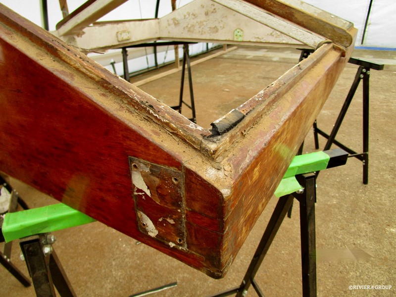
The deckhouse is the next of the deck structures to get the attention of the restorers.


Friday, May 3, 2019

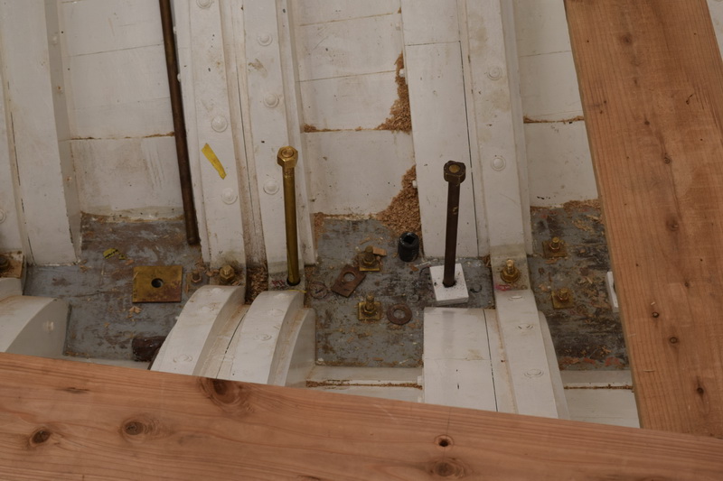
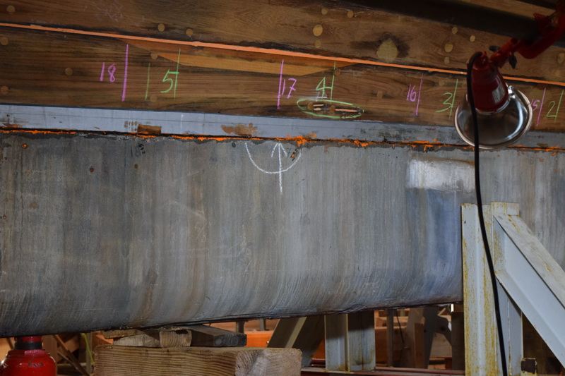
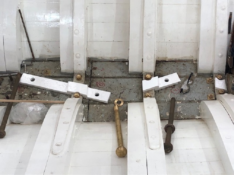
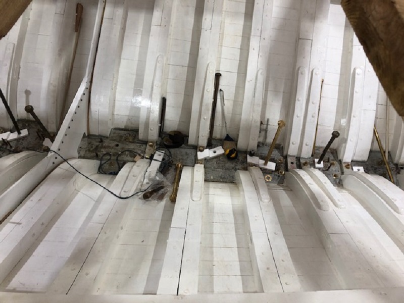
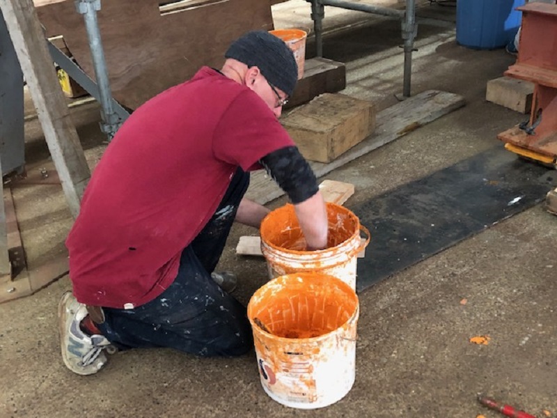
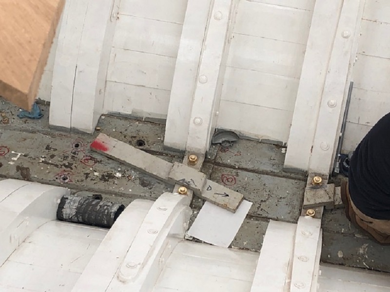
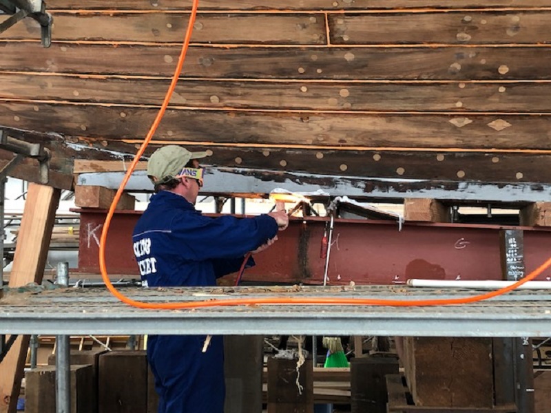
The old keel bolt holes had remnants of white lead and polyester that had been applied over the years. We ground them clean and round with a flat bottom to prepare them to hold the washers for the bolts.


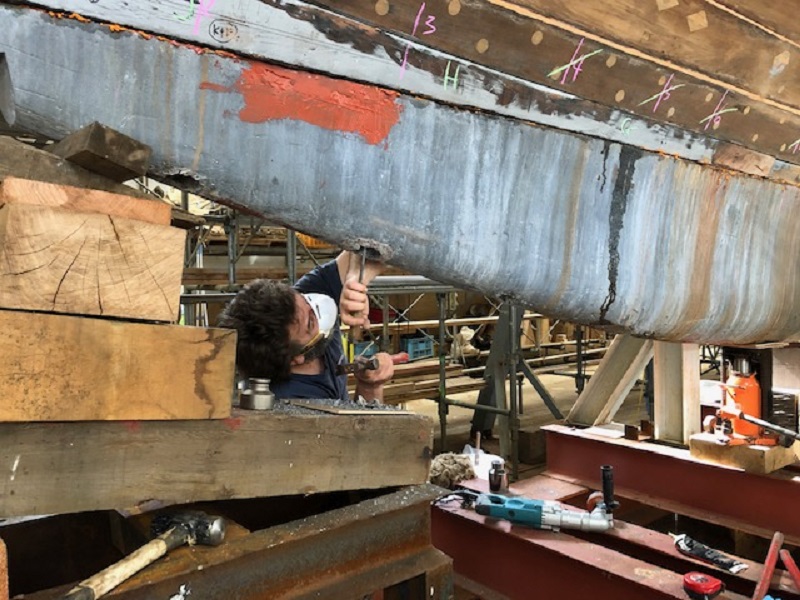
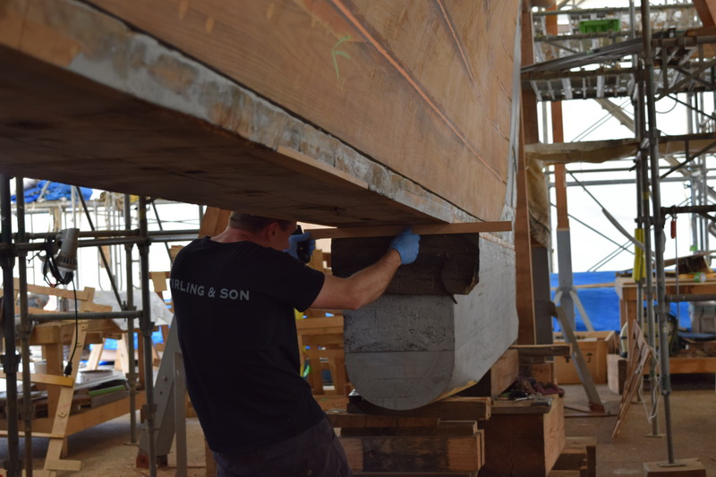
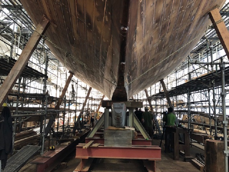
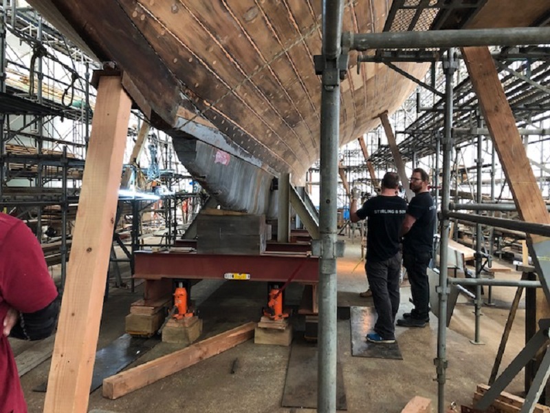
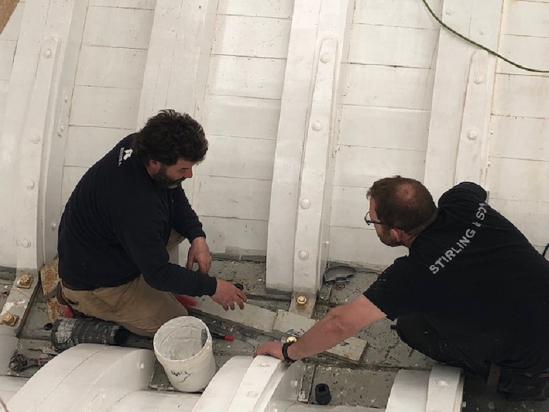
Paul was under the keel making sure of the alignment of the bolts. The lead is so soft that if the alignment is off, the bolt can dig into the side of the hole and jam.


Monday, May 6, 2019

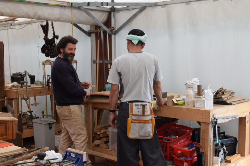
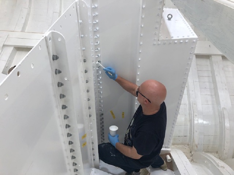
Paul often drops by the interior tent, to check on progress and to make new assignments.


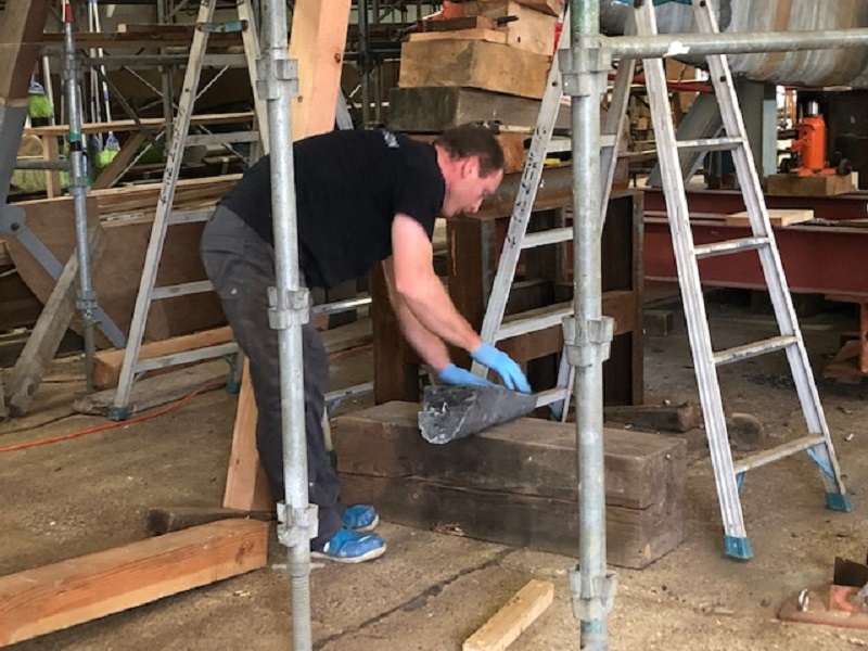
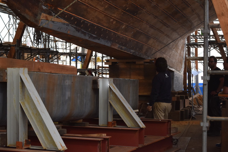
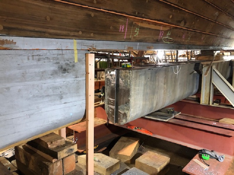
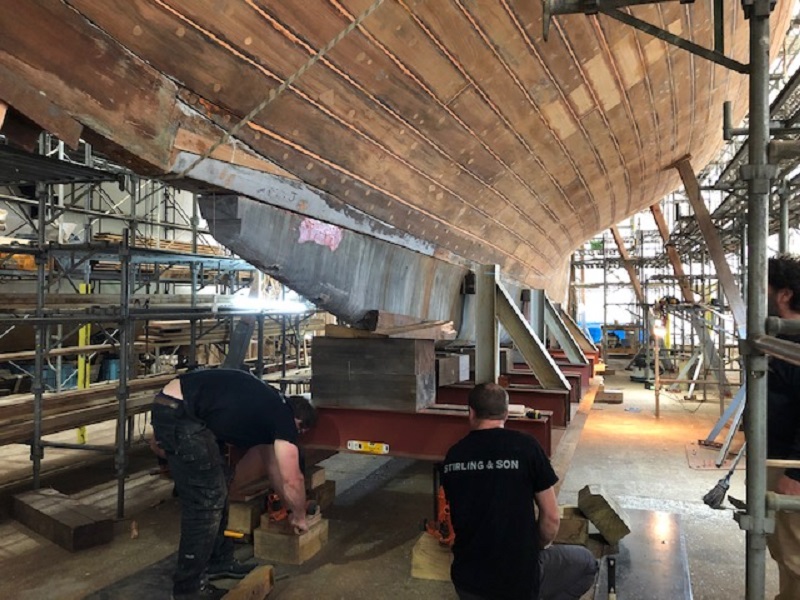
Demetri is shaping a piece of lead to add to the ballast. Sometime in the past, the ballast had cracked at the keel bolt hole at the front tip, where it comes to a point. Someone had fixed it with stainless steel lag bolts into the timber to hold it in place. We cut this part off behind the keel bolt and had a new piece of lead cast with a scarf joint. Then we fitted it to the front of the ballast using the keel bolt and a bronze bolt running through the scarf joint.

Follow Us

Restoration by RIVIERA GROUP

Restoration photos by Yoichi Yabe & RIVIERA GROUP

Text and photographs copyright © 2019
RIVIERA CO., LTD. All rights reserved.
Email : pr@riviera.co.jp

Blog — Tuesday , 30 April, 2019

Blog — Tuesday , 30 April, 2019

Tuesday, April 23, 2019

It’s only April, but inside the tent it is hot enough to feel like summer.


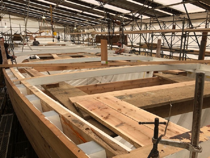
Lewis and Richard are continuing work on the deck beams.


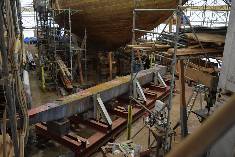
Checking out the keel before bringing the ballast in for installation. Ben had removed the end of the strongback when he fitted the false keel, a piece of wood that fits behind the lead and fills the gap between the lead ballast and the rudder.


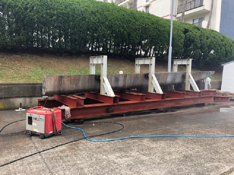
The top of the frame holding the ballast will be removed in preparation for being transported into the tent tomorrow. The ballast alone weighs some 25 tons, so moving it several hundred feet into place under the boat is not an easy thing to do.


Wednesday, April 24, 2019

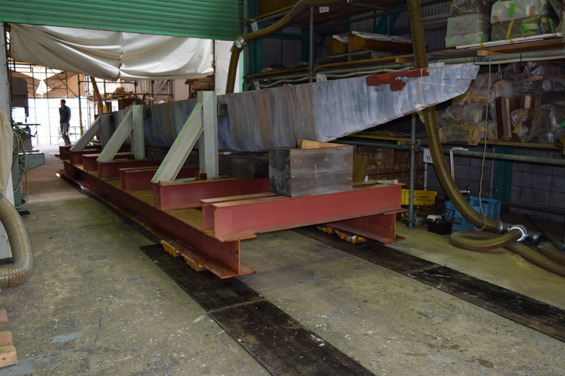
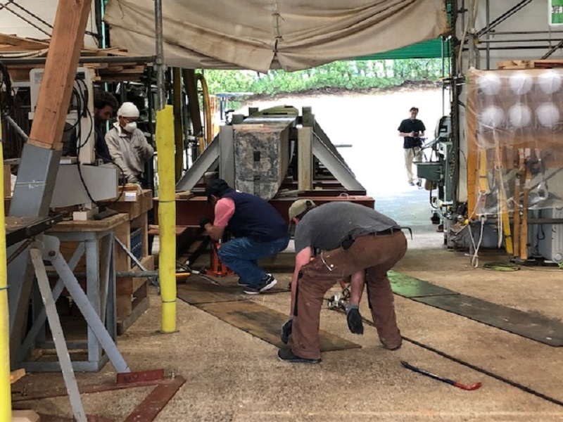
We had to lay down steel plates in the direction of travel and have placed 8 machine skates, two on each corner, under the frame. The skates are meant to carry 6 tons each, so they should be enough for the heavy ballast. The whole contraption was dragged inch by inch into the shed using cable winches.


When set up correctly, the 26-ton ballast and frame rolls very easily, but changes of direction take time and effort (above). The steel plates have to be set in the correct position, and all 8 sets of skates have to be aligned each time. If they’re not aligned right, there is a lot of resistance. Tight turns are the most difficult.


Thursday, April 25, 2019

Today the ballast was wrestled into place under the keel. Staff who weren’t involved were given the day off. As the ballast is being fitted, the ship is only supported on the centerline at the fore and aft extremes, while the shores on each side are keeping the boat vertical. Without the centerline support, the boat is unstable and any work inside her might create unwanted vibrations or imbalance. Until the ballast is in place and the centerline is once again supported, it’s best to keep everyone not needed away from the site.


Friday, April 26, 2019

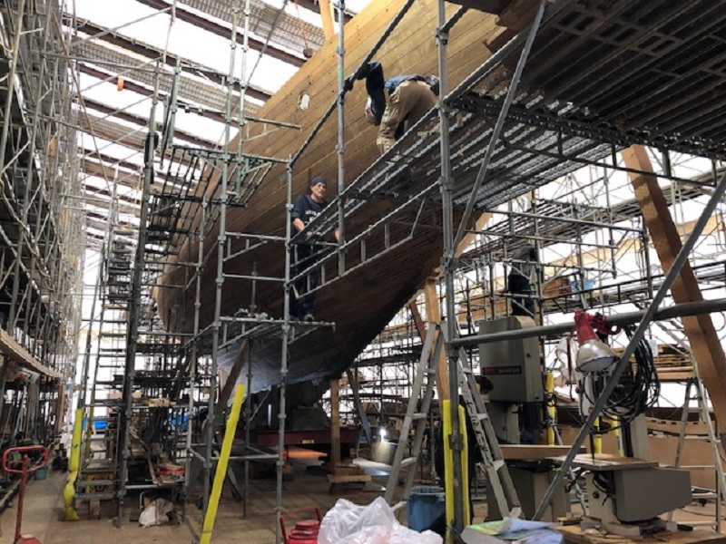
We started today with the restoration of the scaffold that was removed to move the ballast yesterday.


A lot of care is being put into the fitting of the ballast. Originally, the flat end of the ballast (above) was a scarf joint between the false keel and the ballast. We found documents dating back to the early 1930s showing the scarf was cut off and the ballast shortened. This may have been due to a miscalculation, when weight needed to be removed. We decided early on that rather than recast the ballast we would fit a vertical mortice in the ballast and a tenon in the false keel to create a joint between the two. Later, we’ll back it up with bronze plates riveted through both pieces/


“Golden Week,” a stretch of 10 consecutive holidays, starts tomorrow, and there will be no deliveries during that time. We’ve arranged to get the bolts and washers for the keel installation all ready, so we can work throughout the holidays.


Monday, April 29, 2019

Today, the ballast fitting, beam installation, and deck structure repair are continuing. Paul, Ben, Daniel and Demitri have been carefully operating the four jacks at each corner of the frame to raise the ballast and get the bolt holes to line up perfectly.


The hardware to secure the keel from the inside of the ship has been painted, and the keel bolts are starting to be installed.


Lewis and Richard have continued installing the beams.


We had a meeting today regarding the interior walls, furniture, etc. materials. As much as possible we’ll repair, restore and reuse the old materials, but we need to select new material—the same kinds of lumber to match with the old material.


Tuesday, April 30, 2019

The installation of lead keels has reached the climax. Paul is directing.


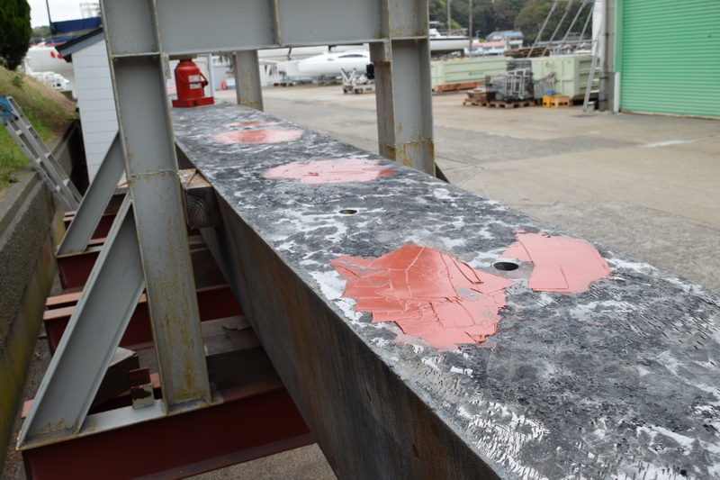
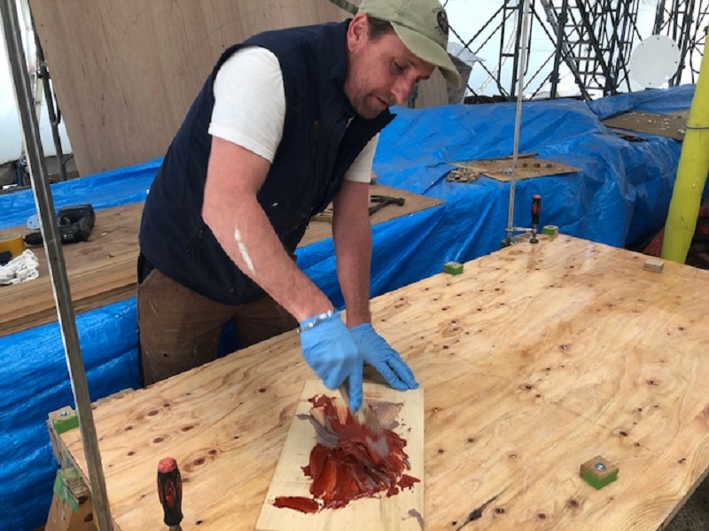
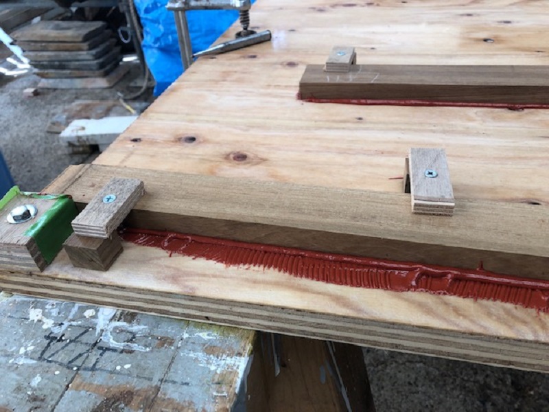
The exact position was determined in the afternoon, and red lead putty was put on the top surface of the ballast and the underside of the wood keel. This created a seal and helped fill any voids or hollows. That wraps up the job of transporting the ballast to its proper place under the keel.


Follow Us

Restoration by RIVIERA GROUP

Restoration photos by Yoichi Yabe & RIVIERA GROUP

Text and photographs copyright © 2019
RIVIERA CO., LTD. All rights reserved.
Email : pr@riviera.co.jp

Blog — Monday , 22 April, 2019

Blog — Monday , 22 April, 2019

Monday, April 15, 2019

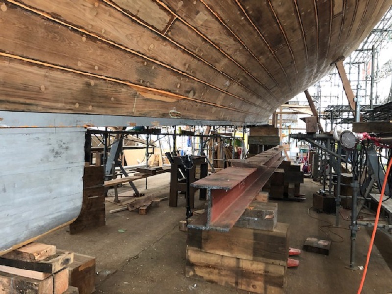
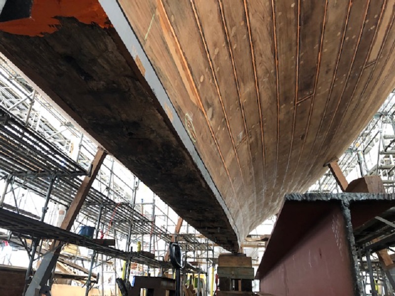
It is time to start preparing for reattaching the ballast to the keel. Above, some of the blocking that elevated the keel over the H-beam strong back is being removed to allow access to the underside of the keel.


Paul, Daniel and Demetri removed the strongback from under the keel. It has been used to keep the keel straight and at the correct angle while we’ve been working on the planks and frames. We hope to install the ballast later this month.


The keel is being supported with blocks while repairs to the underside of the keel are carried out. With the planks and frames in place, now the boat has enough strength to support itself to some degree.


The bulkhead that goes in front of the engine was completed today by Sawamura Iron Works, and we tested to make sure it fits before we install it.


Tuesday, April 16, 2019

Richard and Lewis are using string and a spirit level to set out the deck beam positions.


Daniel is tightening some of bolts that hold down the iron floors. These were inaccessible with the strongback blocking in place.


Wednesday, April 17, 2019

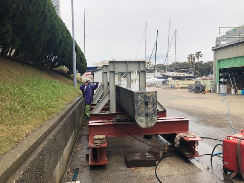
The lead ballast is being cleaned with a high-pressure washer today to remove accumulated dirt before being moved into the tent and fixed to the keel.


Kawashima and Hashimoto continue working on the various deck structures.

The deck caulking for the teak deck arrived today from the American company, Teak Decking Systems. We also discussed air conditioner pumps with our domestic supplier, Marine Elec, and calculated the flow rates for two compressors.


Thursday, April 18, 2019

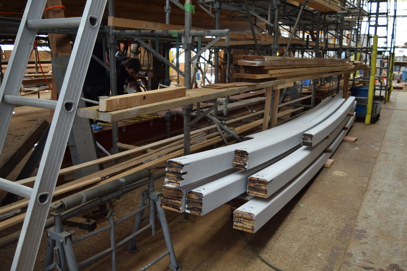
The deck beams have been placed near their final positions.


A Japanese team is working on painting the bolts of the engine compartment bulkhead.

This bulkhead is made of 9 parts, weighing over 300 kg in total.


Paul said he hoped to start moving the lead ballast into the tent by next Wednesday.


Friday, April 19, 2019

Today Lewis and Richard started to fit the beams starting from the near the bow, right on schedule.


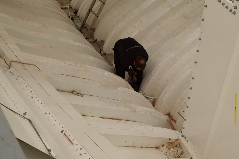
Paul and Daniel are preparing for the ballast installation scheduled for next week. Today the bottom of the ship was being cleaned, and the wrought iron clips inside the bottom of the ship are being mounted. By connecting the keel bolts with these large iron straps over the floor, the whole assembly is strengthened.


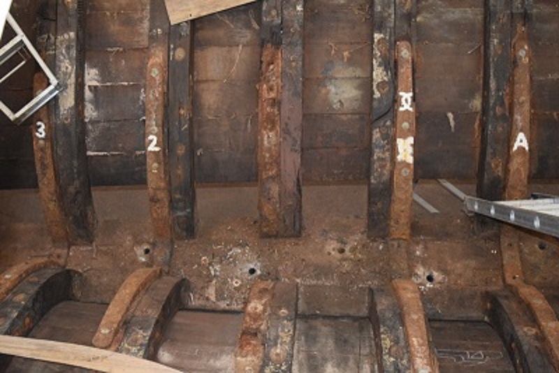
Above: This is what the frames looked like in October 2017, before everything was taken part. Everything is new except for the hull planking and the wooden keel.


Ben did some trial work with the epoxy for the teak deck that arrived yesterday. He was working with a variety of shapes to examine the effectiveness of the adhesive.


Monday, April 22, 2019

Lewis and Richard are continuing to install the beams. They are concentrating on the main beams first—beams that go around the masts or hatch openings, and those that can’t be moved from the drawn positions. Once they finish these, they can set out the other beams and fill in the gaps.


Paul and Graham are installing the chain plates for the wires that support the masts. Paul has been waiting for these to arrive, and when they came in, he started putting them in right away.


The old paint and varnish has to be stripped from all the deck structures as well as the main staircase to find the location of screws, which are hidden by years of dirt and old varnish.


Follow Us

Restoration by RIVIERA GROUP

Restoration photos by Yoichi Yabe & RIVIERA GROUP

Text and photographs copyright © 2019
RIVIERA CO., LTD. All rights reserved.
Email : pr@riviera.co.jp

Blog – March , 2019

Blog – March , 2019

March 1-8

The teak skylight of the main saloon looks battered and worn but after a closer inspection the piece is not in bad condition considering its age. This was true for all of the deck skylights, hatches and companionways. This is a testament to both teak, as a durable timber, and the construction methods at Camper & Nicholsons in the 1920’s. As we’ve said before, nothing was glued during the construction of Cynara. This means furniture can be carefully deconstructed and individual components cleaned and repaired, where necessary, and then reassembled.
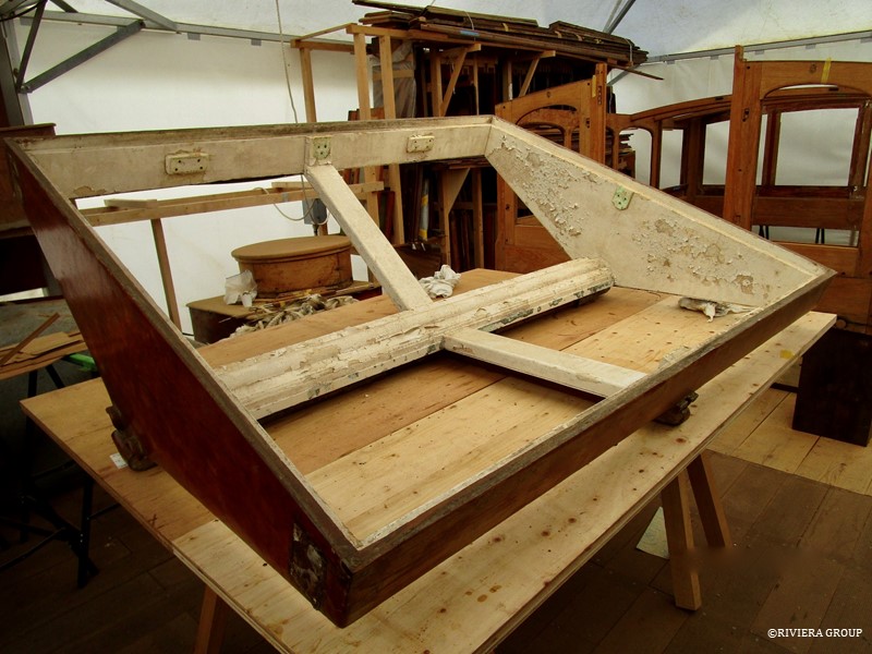
 

The interior of the main saloon skylight had several coats of peeling white paint which would need to be stripped to reveal the glorious teak beneath.
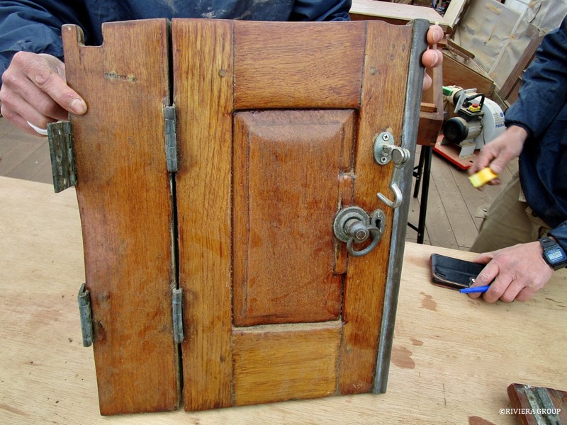
 

One of the doors of the engine room companionway. Here, over-sanding can clearly be seen, especially around the edge of the raised panel in the door. The sharp edges and detail have been rubbed away by over enthusiastic sanders of the past. The frame will be saved but the panel will be replaced. All of the hardware will also be salvaged, cleaned, polished and refitted.
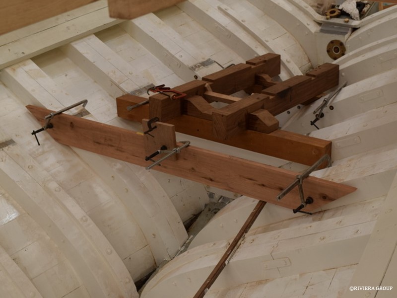
 

The new engine mounts are being tested. A temporary beam is fitted to carry a string line to the propeller shaft center. The propeller shaft is angled so that it misses the rudder tube by around an inch. This means the propeller shaft emerges from the stern post offset to the portside and passes through a faired wooden protrusion called a prop-shaft “log” above the rudder.
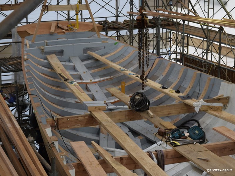
 

Deck preparation is well underway. The sheer clamps that will run the full length of the ship and are part of the support for the deck beam ends, both port and starboard, are laid across the temporary thwarts before fitting. These are a stout 9 ½ by 2 ½ inches (about 240mm x 65mm) of English oak but look deceptively small when laid inside the boat. The aft ends need to fit the extreme curves of the stern and so were steamed and twisted into shape before final fitting.
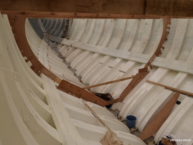
 

A plywood template has been fitted to check the size of the combined old and new sections of the web frame before the installation of the web frames around the main mast. At the main mast and further aft near midship, there is a galvanized steel web frame. This is a heavy steel structure that is bolted to the sides of the wood frames and extends up from the bilge and connects to the deck beams with gussets. This adds stiffness and helps take the loads of the mast and rig in this area. The whole web frame was made in individual pieces riveted together. The upper sections were re-galvanized and re-used but the lower sections in the bilge were replaced due to corrosion.
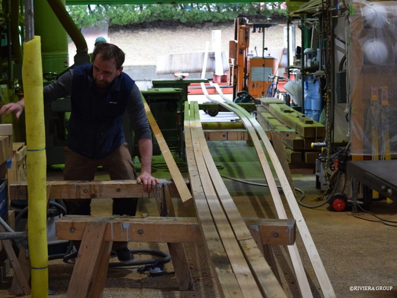
 

Ben struggles to find work space next to the batons being machined next to him. The pine batons snake through the entire machine shop and outside into the gardens beside the workshops. These will be used to find the positions of the stanchions fitted around the deck edge. They are made with pine sections scarphed together, creating batons that run the full length of the ship. Each one is then machined as one piece to make a long and fair baton.
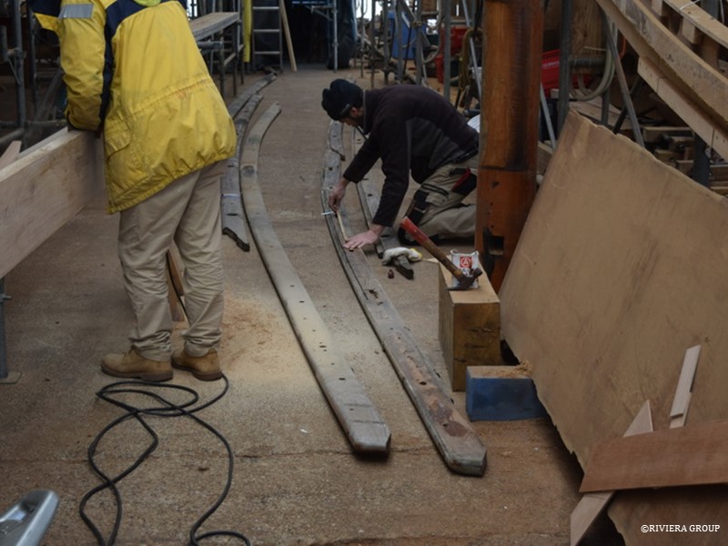
 

Nico uses the original capping rail to check stanchion spacing and position in preparation for fitting the stanchions. A new capping rail will be fitted to the stanchion tops but the old rail holds valuable information and is referred to for important measurements not available on our drawings.
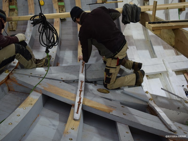
 

Nico drives 5/8 inch copper rivets home through an iron floor fitted just aft of the rudder. The hole for the rudder tube can be seen at Nico’s knee. The floor seen behind Nico, at his feet, is held to the horning timber with giant bronze lag bolts. Directly below is the rudder and propeller shaft and a through bolt is not possible.
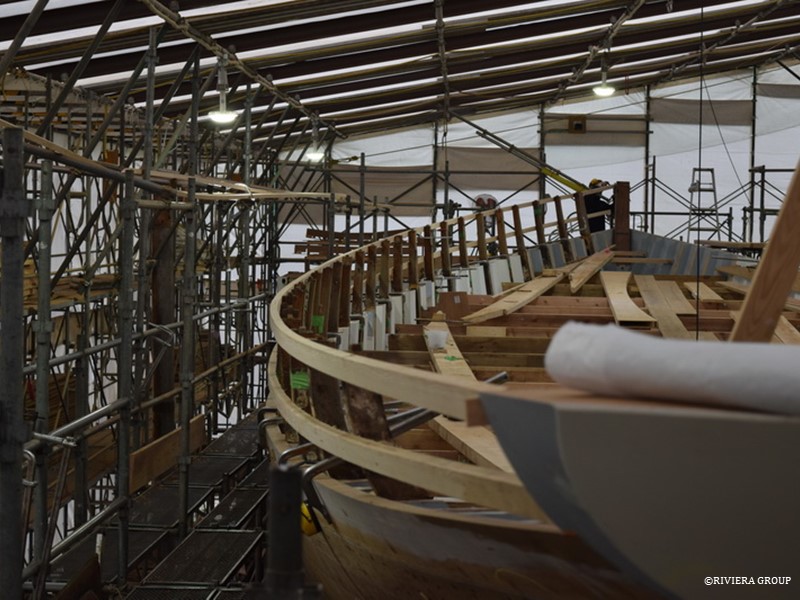
 

Here are the long batons in situ, with the original stanchions being used initially to set up the curve. Original C&N drawings, original wood stanchions and new drawings produced by Paul Spooner Design were used to find the final line. The deck edge, or sheerline, is important to find as a good line greatly enhances the overall look of a ship. This is also true for the top of the bulwarks where the capping rail will sit. Careful adjustment and a keen eye is required. Although many original drawings still existed (courtesy of the London Greenwich Maritime Museum) Paul Spooner played a vital role in checking, fairing, redrawing and providing missing information. When a line was settled on, measurements were sent to Paul Spooner, who checked them on his computer to confirm that the line was indeed fair.


Cynara’s length meant that the full length of the line could not be observed from stem to stern without changing viewing position, and a few millimeters here and there can make a big difference. Cynara also has a slight tumblehome in the bulwark which had almost been lost when she fell out of shape. With new calculations from Paul and carefully positioned original stanchions, all of the curves came together to find the ‘sweet spot’ that creates Cynara’s graceful sweeping lines. New wood stanchions can now be produced to replace the old, one by one, using the batons to show the correct heights and curves needed in the new teak stanchions.
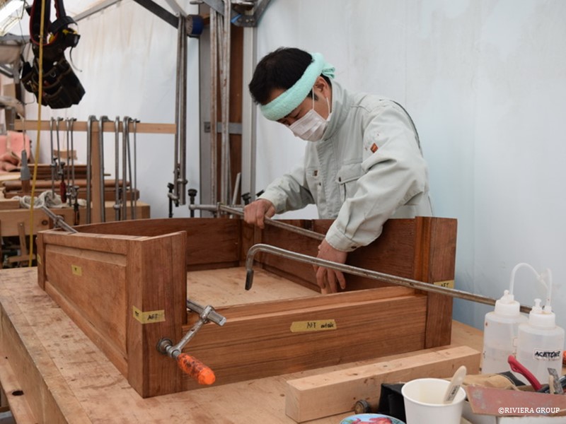
 

Kawashima works on the crew companionway hatch. This is mostly original but new corner posts and door threshold are necessary. The old suffers from split and cracked mortice and tenons and fresh water ingress. This hatch sits on the foredeck and provides access for the crew to the crew quarters in the bow of the ship.
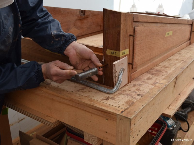
 

Kawashima is fitting the handmade teak dowels driven through the tenons of the joint. This is the exact same method C&N used to secure the joints in 1927.
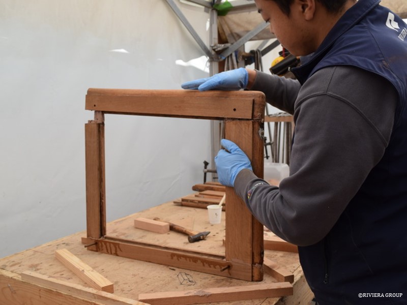
 

Hashimoto reassembles a window frame from the saloon skylight. Local repairs were made using epoxy but the mortice and tenon joints in the frame are secured with teak dowels and prepared with a compound made onsite that was almost identical to what was originally used. It’s always preferable to make local repairs invisible and that’s what the end goal is. We match the colour and grain of the original wood wherever possible. However, an invisible repair is not always achievable, but a repair that can be seen, if done well, can be considered an ‘honest’ repair and becomes part of the story of the piece.


March 11-18
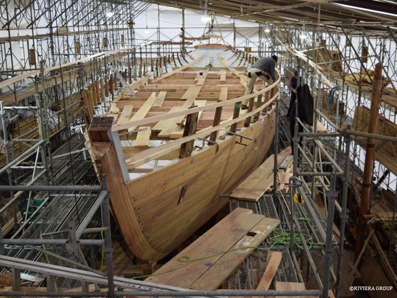
A view from the bow looking aft showing the spider’s web of scaffolding around Cynara.  The starboard side sheerclamp is being fitted at the bow, and the top of the stem will eventually be cut down to accommodate the bowsprit.
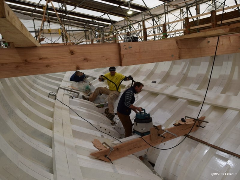
 

With the inside of the frames faired, the paint is touched up and good coat of bilge paint is applied from keel to deck. The position of the engine beds has been confirmed and now, with fresh paint applied, Ben and Richard prepare for a final fit. Before the engine beds are installed however, the last of the centerline bolts must be drilled and fitted here just under where the engine will eventually sit.
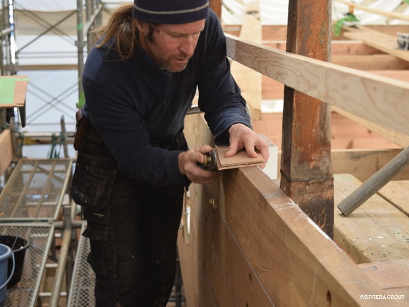
 

Graham works on the teak stanchions that will carry the bulwarks and capping rail. Using the old stanchions gives him a lot of information and provides a three-dimensional pattern to work with. Sometimes a stanchion may need to be adjusted to fit the desired line and here Graham produces a fine wedge to be inserted at the stanchion to adjust an angle. The new stanchion will be produced incorporating the adjustment.
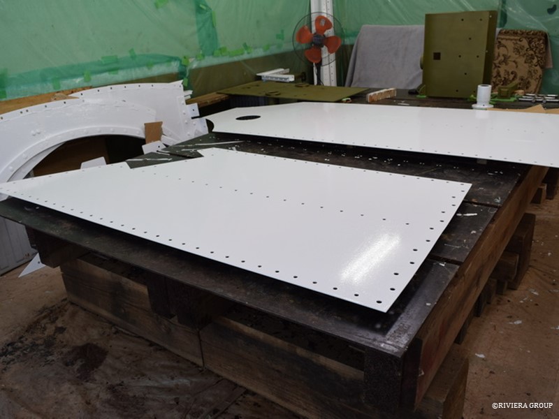
 

These galvanized steel panels will be bolted together to create the bulkhead that separates the engine room from the accommodation area. The original was riveted but for ease of construction, we elected to bolt the new bulkhead. A fresh coat of epoxy paint is applied before installation. In the background are parts of the web frames mentioned earlier, painted and ready for installation.
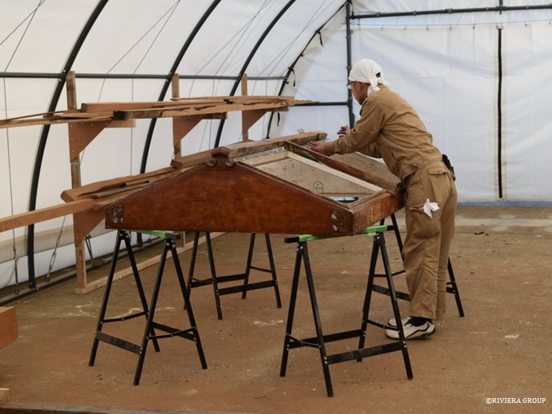
 

Kakimoto begins the stripping process by removing hinges and fittings. He works in an uncharacteristically clean tent. This is because the tent is newly constructed and will eventually be used for spars and rigging. But, before the riggers get started, we can make use of the valuable space it provides.
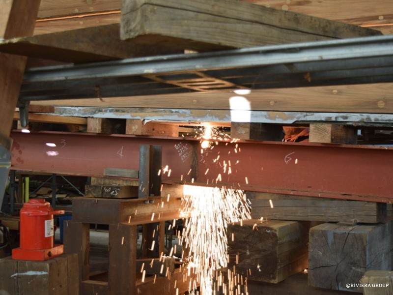
 

Seen here is the heavy H section girder, or strong-back, that used to support Cynara along the full length of her keel. With the ballast keel and the wooden false keel removed, a straight line is created, one of the few outside of the interior. This must be maintained throughout the restoration and the strong-back is used keep this line and support the weight of the ship. Now we are ready to refit the false keel. To fit the false keel, the after end of the strongback must be cut away.
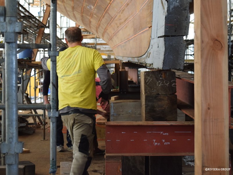
 

Cynara had spent time in the Caribbean (and elsewhere), where ship worm is prevalent, so the original false keel was badly eaten. The wooden false keel is the lowest part of the ship and an easy target for the wood boring clam. Remedial work had been carried out and a protective stainless steel shoe had been retrofitted to the bottom, but the lower part of the false keel was too far gone. It was replaced with bilinga, an African hardwood, instead of the original English elm. The worm had also attacked the area around the rudder head where the rudder tube exits the hull.
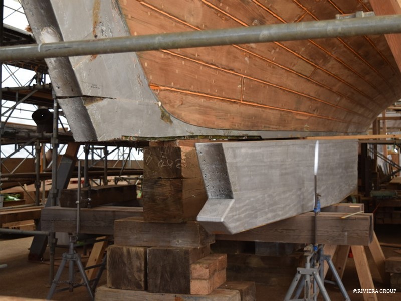
 

The after end of Cynara is supported with blocks in preparation. The false keel sits beside the blocks.
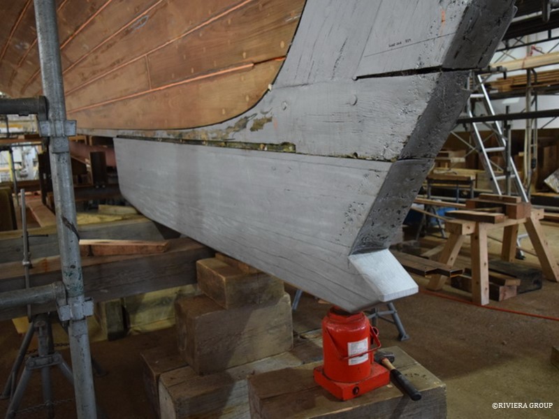
 

The false keel also carries the rudder. So its after end is shaped with a cove to suit the leading edge of the rudder and a rudder bearing that will be fitted at the base. Long naval brass bolts go through the false keel, keel and stern knee to secure the entire assembly. These bolts are directly under the engine and must be fitted prior to installing the engine.
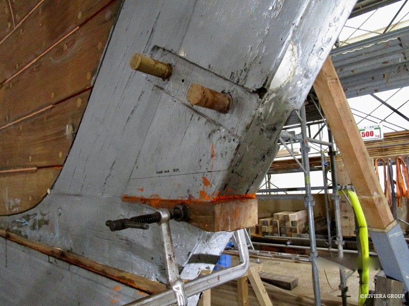
 

The end of the keel had shrunk, creating a gap between the stern post and the keel. A wedge is fitted being careful not to disturb the mortice and tenon joint connecting the two. Wooden bungs are used to close the holes left by the rivets that had previously secured the bronze rudder straps. New holes will be drilled when the straps are re-fitted. The oak stern post is original and although it had dried and shrunk dramatically, it is extremely hard timber and was retained.
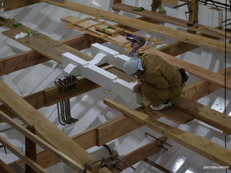
 

Kakimoto applies a final coat of bilge paint before the engine beds are fitted for the final time.
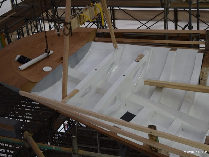
 

The stern area is beautifully finished. Here we see the transom frames which are hull frames and deck beams combined. The originals were cut from single pieces of oak but these are made up of separate laminated pieces bonded together. Fresh paint is applied throughout as Cynara moves to the next phase in the restoration.
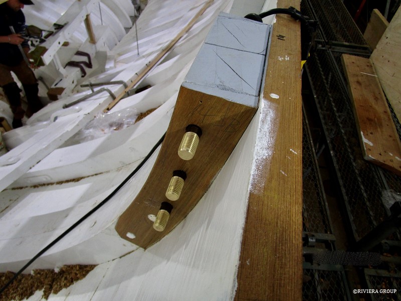
 

These are the mizzen mast chain plate bolts fitted through the frames. The original chain plate bolts were iron and the chain plates themselves were galvanized steel. The new bolts are in aluminium bronze and the chain plates will be stainless steel.
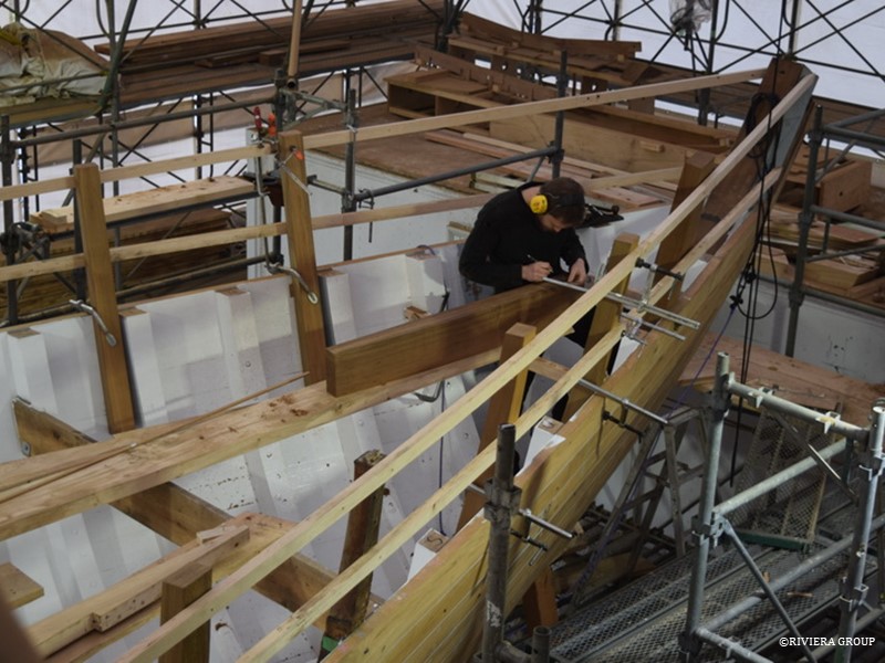
 

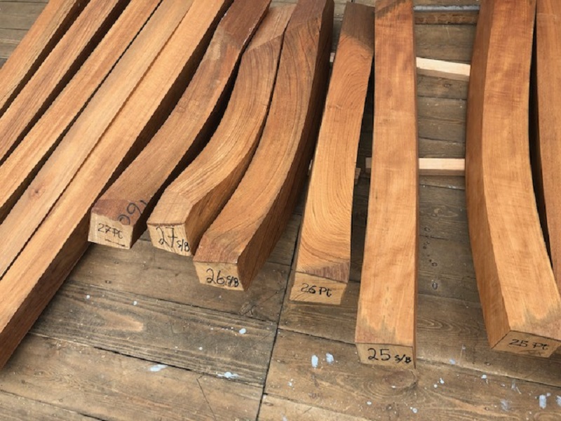
The first stanchions at the bow are of a larger dimension as they also form part of the chocks, or knights heads, that fill the space between the stanchion and the stem. This chock will be fitted with hawse pipes and is solid teak. Mattis works to get these important pieces fitted.
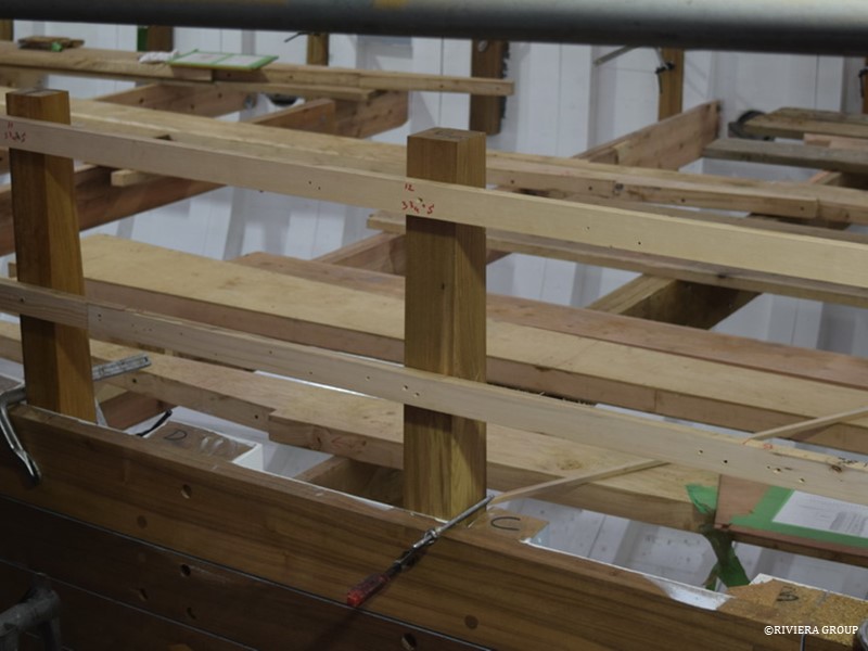
 

Two of the new teak stanchions in position.


March 18 – 28
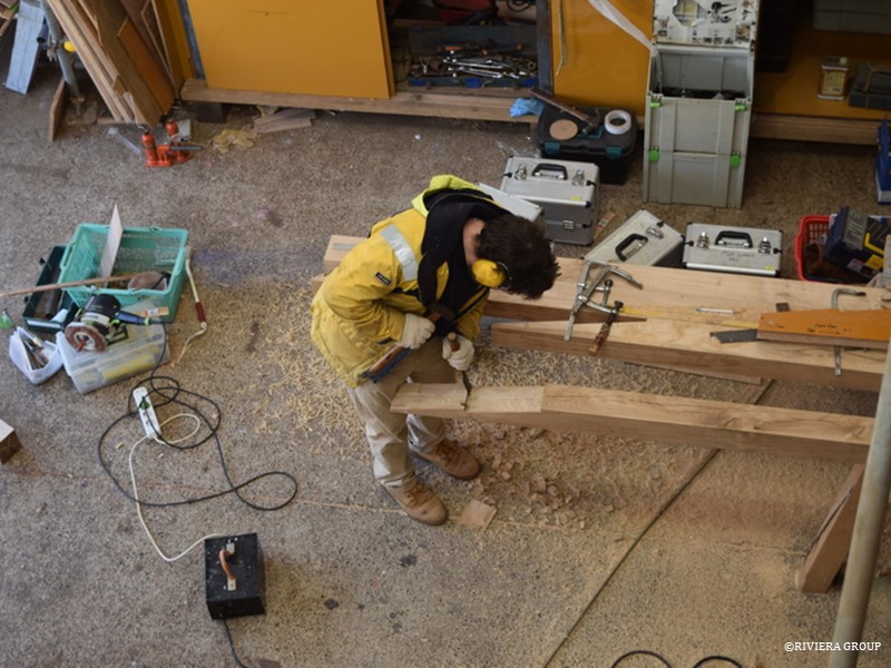
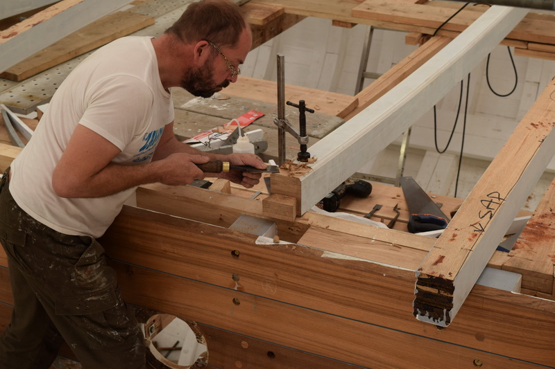
Now that the sheer clamp is finished and ready to fit, Paul works on the beam shelf. Long lengths of English oak are scarphed together and will be riveted to the lower edge of the sheer clamp. The deck beam ends will be dovetailed into the sheer clamp while the lower edge of the deck beam will be housed into the shelf and riveted.
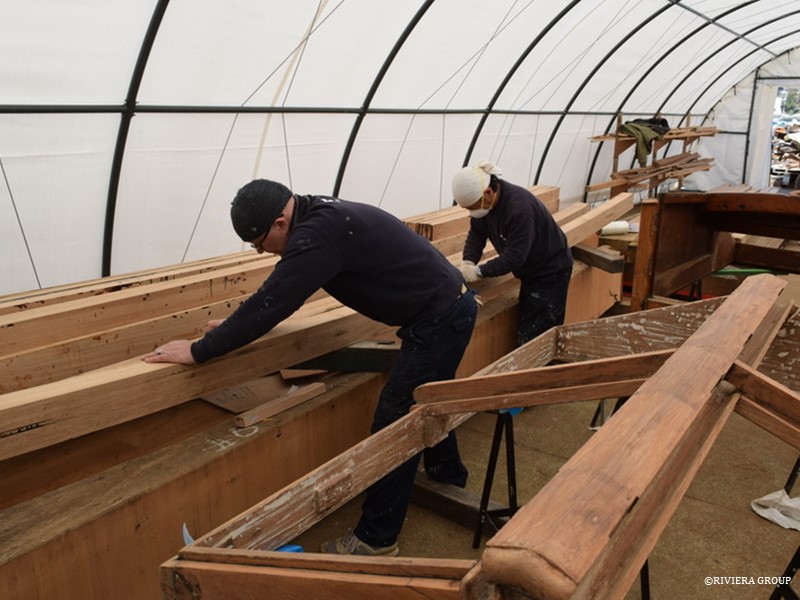
 

Pascal and Makoto sand one of the deck beams prior to painting. The beams will be finished to the undercoat stage before fitting, as waiting until later makes things much more difficult and time consuming. In the foreground is a skylight hatch stripped and ready to disassemble.
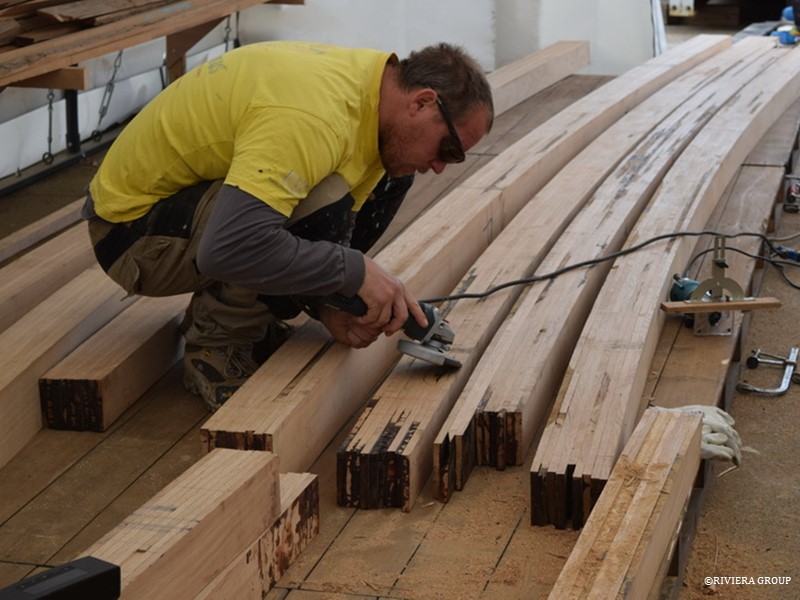
 

Freshly laminated deck beams ready for finishing.
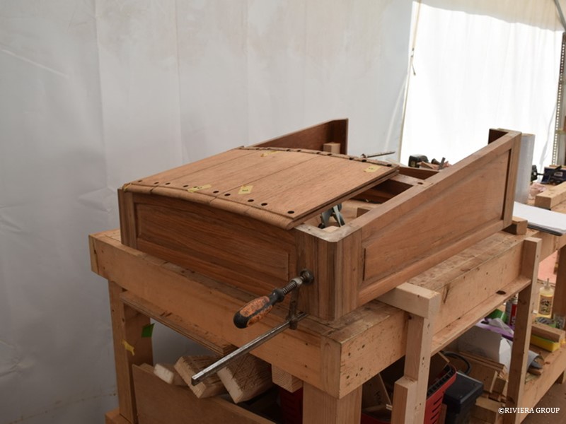
 

The crew companionway hatch has its original planking refitted.
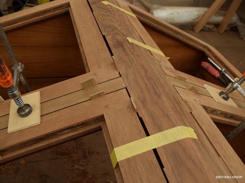
 

With skylight frames reassembled the restored window frames can be measured. Shims and spacers ensure an even gap all around. The next step will be cutting hinges in and fitting new glass to the frames.
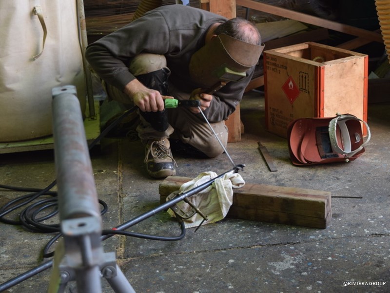
 

Richard welds a drill bit to a long steel rod to bore the holes needed for the false keel bolts.
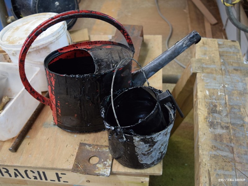
 

A watering can and an old steel bucket are ideal for pouring the melted bitumen tar into the water traps created by the frame-keel junctions. The low points along the keel that would trap water are filled with the tar so that any water finding its way into the bilge will not pond anywhere, but can run freely down to the lowest point where the bilge pumps will be situated.
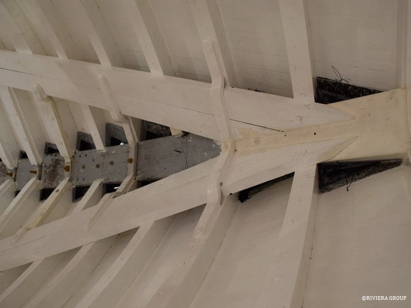
 

Here we see the tar levelling the low spots either side of the stem in the bow.
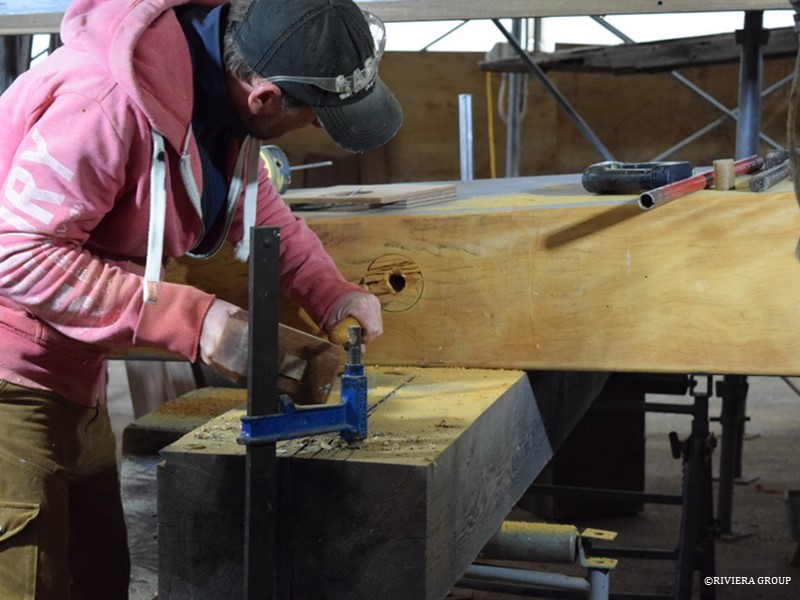
 

Ben cuts one of the counterbores to receive the keel bolt nuts that will secure the false keel.
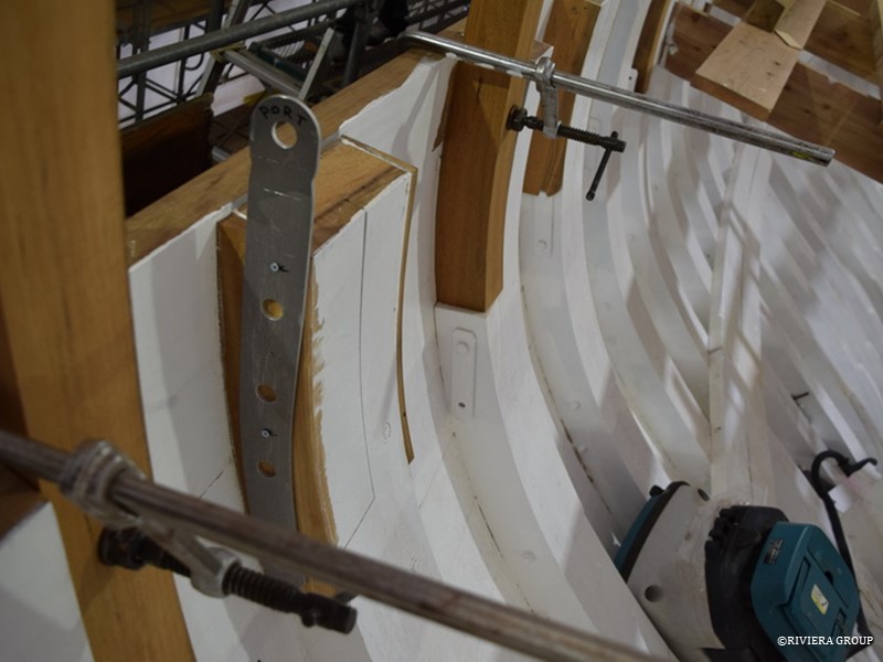
 

An exact aluminium pattern of the chain plates was used to decide the positions for the chainplate bolts in the frames. The chain plates must be orientated so that the head of the chain plate is in the correct final position at deck level to receive the turnbuckles that will tension the rigging.
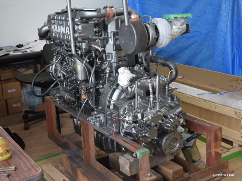
 

The freshly painted and reconditioned engine awaits installation.
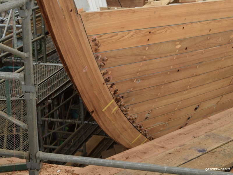
 

Bungs are fitted over the screws in the hoodends of the planking at the bow. Although the majority of the bungs have been fitted and faired, more riveting through the planks will be needed to fit the beamshelf, clamp and hanging knees. The old teak decking was not wasted; it was used to make the several thousand bungs we needed.
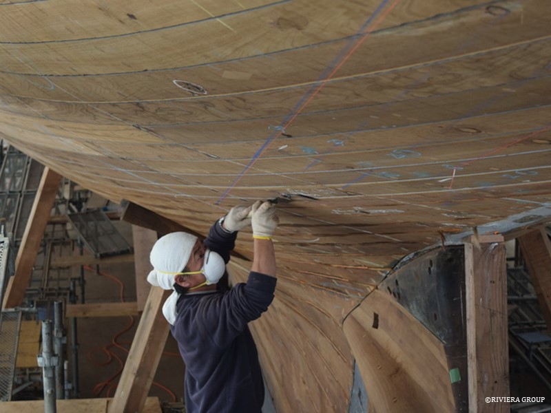
 

Each bung must be cut and faired flush with the planking.
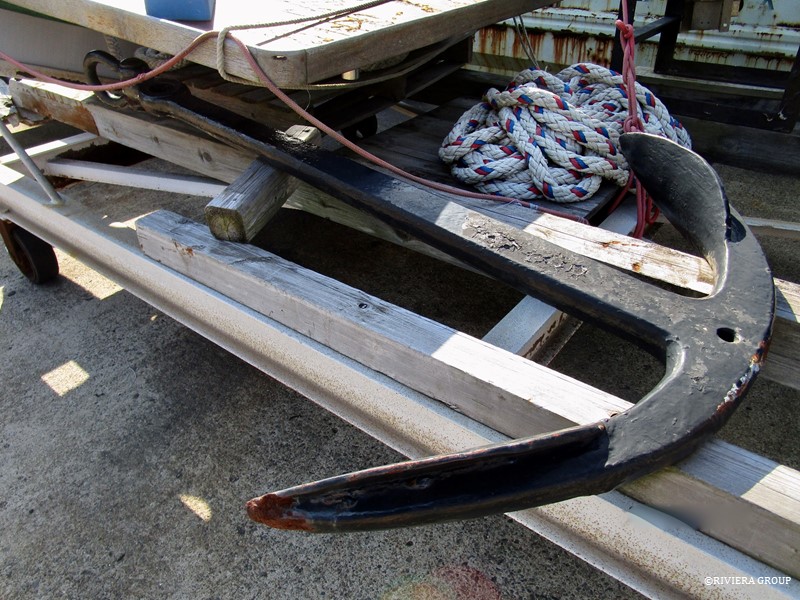
 

One of a pair of original iron anchors from Cynara. These will be cleaned, re-galvanized and re-used. The original admiralty marks can be seen under the many layers of old paint. We ordered two new anchors, but when they arrived, one glance told us the workmanship of the originals was much better, so we changed our plans and rebuilt the old ones.
 

Follow Us

Restoration by RIVIERA GROUP

Restoration photos by Yoichi Yabe & RIVIERA GROUP

Text and photographs copyright © 2019
RIVIERA CO., LTD. All rights reserved.
Email : pr@riviera.co.jp

Blog – February , 2019

Blog – February , 2019

January 1-8 , 2019

Makoto is cutting bungs flush with the hull planks. All in, there are thousands of bungs that all need to be cut, fitted and finished one by one.

The freshly painted bilge. Hopefully this coat will be more successful than the first. Battens are nailed against the frames to create something to stand on when climbing up to reach the higher planks and rivets. Temporary bolts can be seen at the centerline which will be replaced with ¾” diameter, square-headed naval brass bolts that will secure the throats of the wrought iron floors to the keel timber. These are not the keel bolts which are fitted between the floors. One floor is fitted at each station or frame pair.


Above. Dan and Leo from Stirling & son get started on the initial fairing below the waterline with power planers. Once the planking is fair, sanders will be used to remove tool marks. Because the old planks have been sanded before during their lifetime (possibly many times), and are now snugged hard against the new frames, some plank edges are proud and need to be made flush with their neighboring plank.

As much attention will be paid to the fairness of the planking below the waterline as above it But longboards will be used above the waterline to achieve a good, fair surface for painting and a finer finish than is needed below.


Jonathan has been called in from the joiners shop, where he’s working on the main deck house, to help with the final strakes. All hands are needed to get the planking finished as soon as possible so that the caulking team can move ahead.


Demetri checks frame fairness with a ribband at the counter stern. Adjustments are made where necessary to ensure the planks fay nicely against the face of each frame.


A light inside the hull highlights the shape and shows clearly the twist in the transition from the counter into the midships


The last four strakes on the port side are laid together to measure their combined width. Using old planking means the gap left by the fitted planks has to be carefully monitored so that there is enough space left for a good fit with the final strakes. With four to go, the strakes can be adjusted 1 or 2 mm from the edges to allow for adjustment. A spline can be glued to an edge should the space be too wide. A combination is the most likely outcome so that the plank edges have fresh and fair caulking seams. An even gap is the most important factor.


Dan works at the stern post fairing the junction between the stern post and prop shaft log. This is a complicated shape and has the tightest curves in the hull.


Cynara’s starboard side (here looking aft) is complete after a first fairing and is looking in good shape. Further fairing will be done after the caulking.


The inclinometer shows the angle of heel when the ship is underway. Although certainly very old and part of Cynara’s inventory for many years, it is not thought to be an original part from C&N. However, as we believe it has been onboard from her very early days we decided to restore and refit. The inclinometer was shipped to Greybeard Yachting in the UK for restoration.  


Richard Sills, our resident engineer, is helping fit floors in the stem area. The floors are drilled for 5/8” copper rivets that are driven through frame and planks. Drilling must be done with great care to avoid existing fasteners and reuse the previously counterbored hole in the original planking. Plugging and re-drilling a fresh hole in the plank is an option but this would render the plank too weak. Using the original holes is slightly more difficult but maintains the overall strength needed in the teak plank over the frame.


Even though the last strakes are still being fitted, Will Stirling starts with the caulking process on the lower planks, first concentrating on the butt joints. Traditional caulking with oakum is a skill and trade in its own right. The oakum not only seals the joint between planks but also adds stiffness to the hull. Knowing how much and how hard to apply the oakum can only be learned by experience. Cynara’s oakum was laid in several layers making sure to fill the entire seam leaving just enough space to finish with red lead putty below the waterline and teak splines above.


One of the butt joints after caulking


Dan gets started with some caulking, giving the oakum a gentle twist before hammering it into the seam


Graham and Mattis at work at the stern, where there is the added difficulty of making sure the hood ends fit well at the stern chock. There is a lot of twist here and a fair plank line must be maintained.


February 8-15

The hull looking aft. The planking is almost complete, with only single strakes left, port and starboard. Arthur, a French shipwright, can be seen working at the bottom left of the picture. The position of the engine beds can be considered at this point, and construction planned. There is more space before the main engine room bulkhead is installed and restricts movement in this area.


Joaquin Fernandez of Stirling and Son caulks at the hood end of the port side garboard strake. Joaquin is a Spanish boat builder currently working in the UK and belongs to the specialist caulking team.


Mattis works on one of the last strakes to be fitted.


With the lower bilge complete, Ben has begun working on new timber engine beds. Although they are still strong, the old beds were built for a different engine and have had multiple alterations and modifications over the years. Cynara has probably had several engines before the current Yanmar and this was our opportunity to make beds that fit this specific engine. Next to Ben is the oak beam shelf, which is being prepared while the final planks are being fitted, and the long, hooked scarfs in the end of each section.


Richard starts preparation for the engine and engine bed installation.


February 15-22

The penultimate strake at the stem goes in with the help of clamps and wedges.


The final strakes will soon be fitted and so the end is in sight for the planking. Attention is now turning to the next phase of the restoration. The stern chock has had an initial fairing and Cynara’s name is being set out on the face of the chock. While the chock is not finished different letter sizes and fonts are being considered.


Now that the planking is on track, the focus is back in the joinery shop where we continue to methodically restore the main deck house. The original construction method allowed us to completely dismantle the entire structure. In fact, no glue at all was used in Cynara’s entire original construction. Our intention is to follow this approach. Though modern glues are used to affect local repairs that would not allow us to otherwise salvage original parts, each component, whether original, repaired or new, is jointed traditionally with tenons, wedges and dowels. Cynara is almost a century old and the deck house and the other deck furniture was in good shape, so why change now? Glue does not substitute for good joinery. With only local repairs of individual pieces the vast majority of the main deck house is original.


Richard checks the bronze steering gear. This is an original and will be refitted. The worm gear, cog, and the rudder indicator have been returned from Deep Blue engineering in the UK where we sent them for refurbishment.


February 23-28

Mattis hammers home the shutter plank. This is a significant moment in any build.


Dan and Joaquin prepare oakum before caulking. The oakum is taken off the bale, teased out and rolled. This creates a long even strand of the correct size for the seam without lumps or thin parts. It also makes caulking easier and more consistent as they work along the seams.


Along with the return of the steering gear parts came the rudder tube that carries the rudder post and the original bronze fairleads that have been refurbished with new bolts through the central rollers and a good polish. Also visible is our stock of naval brass and copper rod in various diameters which are used for the necessary rivets and bolts.


Paul fits blocking at the stem head between the stem and the first frame. Blocks of oak and teak are used between selected frame heads that will carry bolts or rivets. These blocks at the stem will give the end of the beam shelf something to sit on and will also take the bolts from the knight head chocks that will create the forward end of the bulwarks when fitted above.


When caulking is complete, the seams and oakum are painted with linseed oil and red lead. Finally, red lead putty is payed into the seams. 


Kawashima and Pascal drive home the last rivets and dumps on the shutter planks.


Attention now moves to the wood stanchions. Although the original teak stanchions appeared to be in good condition, they had suffered damage from fresh water ingress, so it was decided to replace them. The old ones are used to set up the line for the capping rail and as patterns for the new ones. Minor adjustments can be made before new teak stanchions are cut.
 

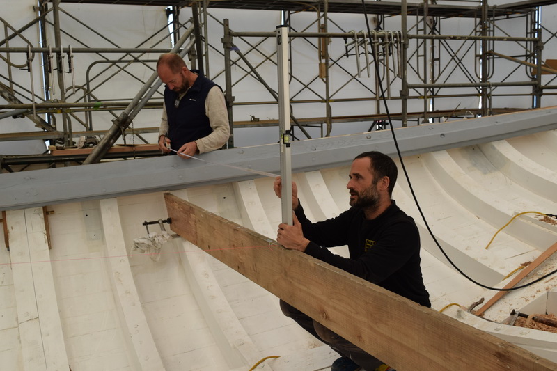
The height of the rail is checked against the C&N drawings and what is found using the original stanchions in position. Having the original stanchions made finding ‘the line’ much easier.


Above, here we see a slight tumblehome at the midship section, where the hull becomes narrower above the waterline. This is an important detail that greatly affects the overall look and the final shape and appearance of the hull if miscalculated or ignored.


Bevels, bolt and rivet positions are checked and marked and minor adjustments made so that the new stanchions will carry the correct bevels and curves to fit the planking snuggly. Any other adjustments are noted and transferred to the new timbers.


Looking back at the stem with planking complete. We’ve reached a very satisfying point in the build. Now that we have a hull, we must change focus and start looking towards the deck and its accompanying knees and hardware. Also, while the teak stanchions are cut and fitted, a first fairing of the planking can be started along with the caulking of the topsides. The hull is not ready for a final fairing as more bolts and rivets with their attendant bungs will be needed when hanging and lodging knees are fitted at the deck beam ends. These must be fitted before fairing is finished as adding rivets and bolts may move the planking and ruin any previous fairing.
Follow Us

Restoration by RIVIERA GROUP

Restoration photos by Yoichi Yabe & RIVIERA GROUP

Text and photographs copyright © 2019
RIVIERA CO., LTD. All rights reserved.
Email : pr@riviera.co.jp

Blog – January , 2019

Blog – January , 2019

January 7-15 , 2019

Above, Mattis prepares to cut one of the new sheer planks. Cynara’s teak planking was in remarkably good condition for a yacht of her size and age, with the high-quality teak withstanding most of the hardships of a life at sea for almost a century. But some of the old planks were damaged and distorted to the point where the entire strake, port and starboard, was deemed un-serviceable.


Demetri, a young English shipwright, makes a pattern to replace a short plank at the end of a strake at the counter stern, just above the rudder. He originally came to help with the caulking of the hull with the team from Stirling & Son, shipwrights from Devon England. The team was booked to help caulk the boat, therefore freeing up our “in-house” shipwrights for other tasks. Unfortunately for them, we were not finished planking. Fortunately for us, they were happy to help wherever needed.

Here, in the counter stern, we can see how the hood ends of the planks are “snaped” or “joggled” (depending on where you’re from) into the oak horn timber at the centreline. This eliminates feather edges or thin sharp points at the plank ends that would break away with the pressure of the caulking. It also locks the plank into the centreline.


Nico is setting up the clamping system for another plank to be fitted. Before a plank is fitted the backs of the frames are checked for fairness. Oak clamps made from threaded bar and oak square section are set up at the correct height for the plank. When tightened around the fame pairs, wedges can be used between the clamp and the plank to edge set the plank into position and create a tight seam for caulking. “Edge set” means that a straight plank is bent edgeways to follow the plank line around the hull. This makes cutting planks from stock very fast and economical.


One of the completed oak bilge stringers in place at the stern.


A view looking aft from the stem, showing the double bilge stringers being fitted. Only the port upper forward section remains to be done (it can be seen laying at the center of the photo). Kawashima and Mattis are preparing to lift the heavy section into place. The line of the oak clamping system reveals the height of the fitted strakes on the outside of the hull.


Richard Works at the sheer line. The sheer line is established using a stout pine baton or ribband to mark the line. Each frame top is marked, taking the deck camber into account. This means that the top of each frame pair, port and starboard, is cut at a different angle to match the angle the deck strikes the deck edge at that position.


With the frames marked for the sheer line, the extra timber at the top of the highest futtocks is cut away. Here Richard cuts the frame tops at the bow.


Nico is at the stern, working on the plank end of the last strake to be fitted. With the new frames in place, the heavy steel box section ribbands have been removed and timber ribbands employed to maintain the fairness of the hull.


Nico inspects one of the single frame ends in the stern where it meets the horn timber. The frames here have a mortice that fits a tenon in the horn timber and is bedded in wet paint, linseed oil and red lead putty. The corner of the frame foot, where it meets the horn timber is cut away, creating a hole for water to drain from the counter stern into the main bilge. The red putty line running horizontally here marks the scarf joint that connects the new horn timber section aft to the original forward section.


January 15-30 , 2019

With the sheer strake fitted, the second strake is quickly taking shape. Here we see a view looking forward on the starboard side. The scaffold is set at a convenient height but with a planking team working below, the scaffold walkway heights will need to be re-arranged depending on which team is working where. Fortunately, this type of scaffold was quick and easy to adjust. The strake seen between the two ribbands is fitted with temporary fasteners to help maintain a plank line and fairness in the frames. As the gap between the upper and lower strakes closes, the plank line must be carefully observed so that the space for the last strake is not too big or too small. This is especially important when re-using original planking.


With the new sheer strake fitted, holes for fasteners are marked and drilled. Each hole is carefully noted in chalk to denote if it is for a rivet, screw or nail. Mattis works on the second strake down from the sheer. We can now fit planks from the sheer down. This, in theory, means planking should go twice as quickly with four planking teams working at one time, instead of two. The high and the low planking teams can be seen here working on the port side.


Kawashima is working on a lower strake with Mattis working on the strake above. Care must be taken with tools in the scaffold and loose tools left on walkways is forbidden.


Richard secures the hood end of the second strake at the stern chock.


The view from the scaffold showing progress so far. With the top strakes fitted, the beam shelves and clamps will soon be ready. Deck beams are also being prepared at this time.


Richard checks the size of the caulking seam between two planks. Even if the back edges of the planks touch, which is good, an even gap on the outside of the seam is necessary so that the caulking can be driven home evenly and allow room for the caulking irons. Even though these seams will eventually be splined, an even and fair seam line will make caulking and splining easier.


Nico is closing the gap between upper and lower strakes.


Cleaned and prepared planks lay waiting to be fitted. Each plank is assigned a letter and number indicating its position on the hull.


A new sheer plank can be seen here, where it meets the new laminated stem section with a new plank fitted under. The sheer plank and to a lesser extent, the one below it can take a lot of abuse over the years, due to bumps from wharves and jetties, bumps from other boats moored alongside, a bump from an anchor fluke or a minor collision.  However apart from these two and some planks adjoining major skin fitting, nearly all of the other planks we are using are original.


The planking team is now at the portlights. Getting the original planks to fit exactly as they were, creating a clean hole for portlights in the correct position, took some planning. The end result was good. There was some damage from old portlight fasteners but nothing that warranted a new plank. We will make some local repairs to secure the original refurbished bronze portlights.


Before the beamshelf is fitted,  teak and oak blocking is installed between the frames against the planking. The blocking is placed where there will be knees, deck, or rigging fittings that have fasteners that pass through the deck or the planking. The blocking eliminates voids where there will be rivets or bolts. Fitting the blocks now will be far easier than after the beam shelf is in place. We used off cuts of teak wherever possible but some oak is also used, if its dry enough. If the oak is not dry it will shrink and distort.


A nice shot, looking aft, of a clean and framed hull with stringers in place, waiting for a better coat of paint. The oak clamps reveal that the last strakes are being fitted on the exterior. The pine thwarts at deck level maintain the deck profile. Without these, the hull would be surprisingly flexible. By this stage, the hogging has been eliminated and the hull shape and sheer-line restored.

Follow Us

Restoration by RIVIERA GROUP

Restoration photos by Yoichi Yabe & RIVIERA GROUP

Text and photographs copyright © 2019
RIVIERA CO., LTD. All rights reserved.
Email : pr@riviera.co.jp